
Return Filling Valve

A technology for filling valves and valve seats, which is applied in packaging, bottle filling, liquid bottling, etc. It can solve the problems of sanitation, difficult filling valves, scaling and other problems, and achieve the effect of reducing costs

Active Publication Date: 2018-02-27
GUANGZHOU TECH LONG PACKAGING MACHINERY CO LTD
View PDF7 Cites 0 Cited by
  • Summary
  • Abstract
  • Description
  • Claims
  • Application Information

AI Technical Summary

Problems solved by technology

And when there are empty bottles to be filled again, the temperature of the beverage that has just flowed into the bottle is lower than the required 90±1°C, and because of the low temperature of this part of the beverage, the microorganisms in the shelf life will exceed the standard, and there will be hygienic problems. Beverages that cannot meet the requirements can only be discarded, and the longer the bottle-free time, the more beverages will be discarded
[0003] In addition, when performing CIP cleaning, the cleaning cup is moved up by the lifting mechanism, and the mouth of the cleaning cup is in close contact with the container seal and then sealed with the outside world. At this time, the sliding body is separated from the valve seal, the filling valve is opened, the CIP liquid flows into the cleaning cup, and the air in the cleaning cup flows into the material cylinder through the air return port. When the liquid level in the return air pipe and the liquid level in the annular cylinder When it is flush, the CIP liquid stops flowing, and the inside of the filling valve is in a static soaking state of CIP liquid. If the filled product is fruit juice or dairy products, it is easy to scale inside the filling valve, so this soaking cleaning The method cannot remove the scale, and it is difficult to clean the inside of the filling valve to meet the production needs

Method used


Image

  • Return Filling Valve
  • Return Filling Valve
  • Return Filling Valve

Examples


Embodiment Construction

[0025] Embodiments of the present invention are described in detail below:

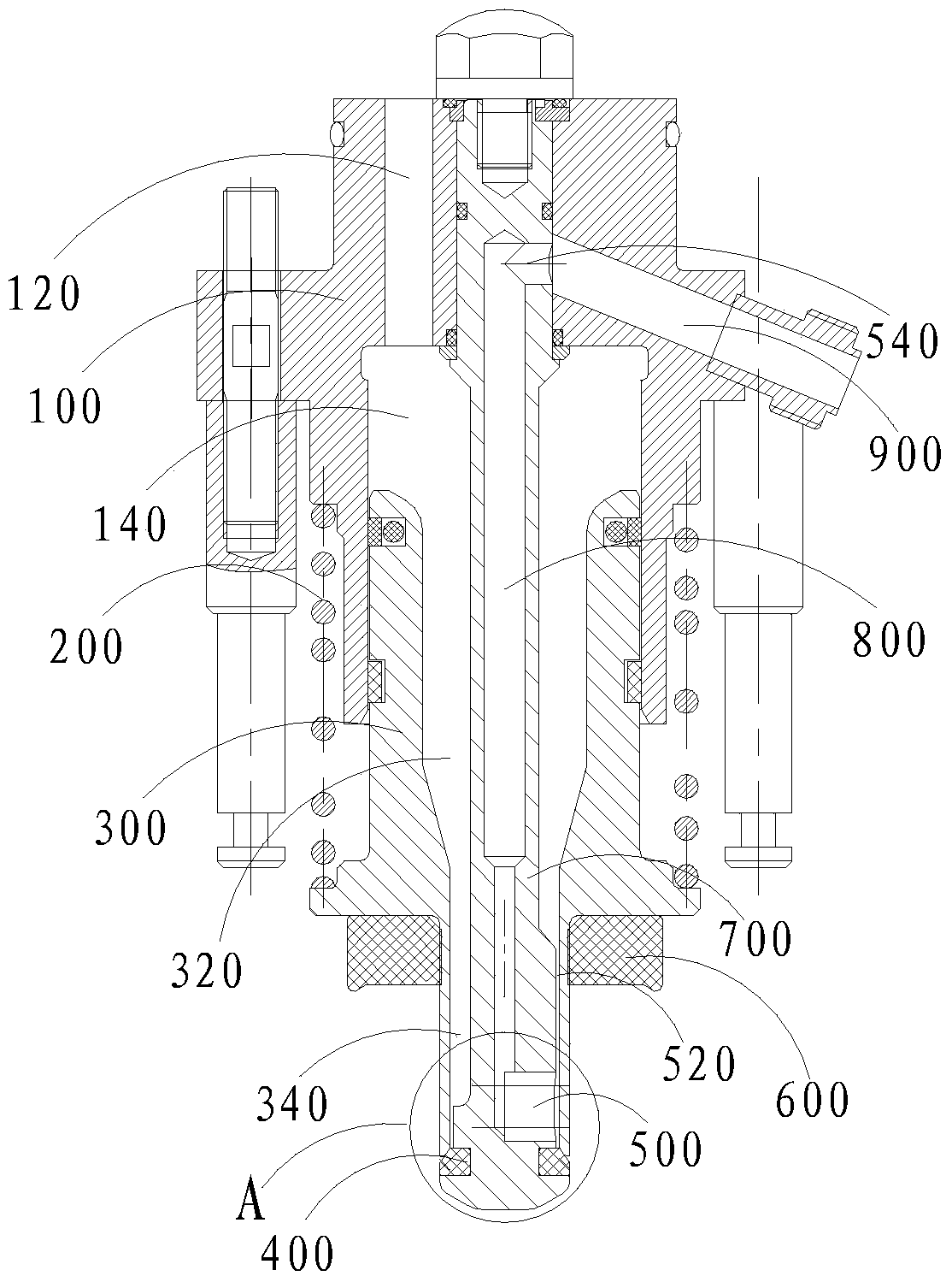
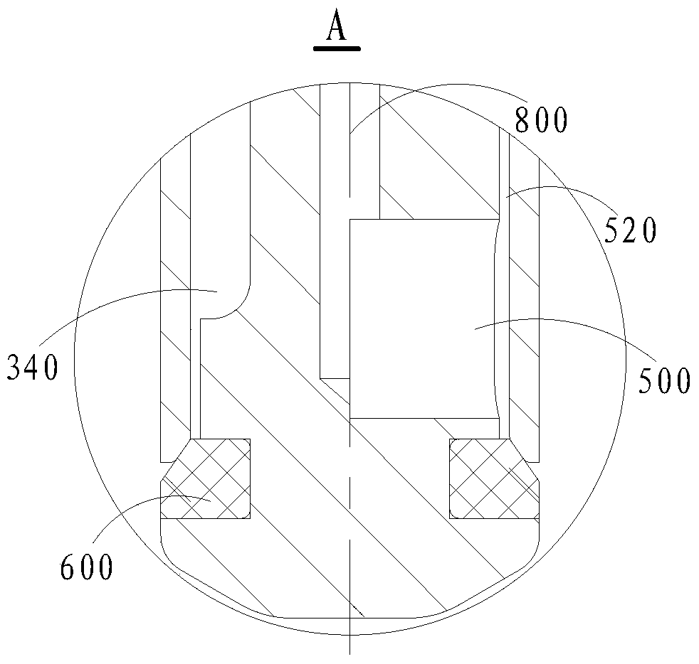
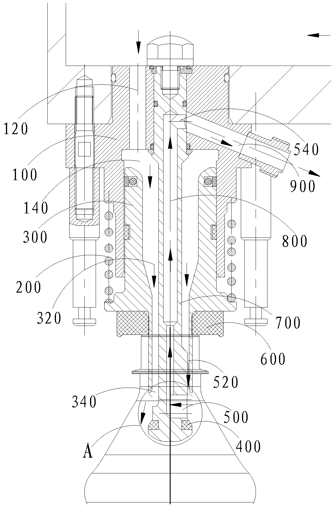
[0026] Such as figure 1 , figure 2 As shown, a backflow filling valve includes a valve seat 100, a valve core 700 and a sliding body 300, the valve seat 100 is provided with a liquid inlet channel 120 and a liquid outlet channel 900, and the sliding body 300 is slidably fixed on the On the valve seat 100, a filling passage 320 is provided between the sliding body 300 and the valve core 700, a valve seal 400 is provided at the lower end of the valve core 700, and a gas return valve is also provided on the valve core 700. Return channel 800, when the sliding body 300 is in the first state, the sliding body 300 contacts with the valve seal 400 to seal the filling valve; when the sliding body 300 is in the second state, the sliding body 300 and the The valve seal 400 is separated, and the liquid inlet channel 120 , the filling channel 320 , the gas return and return channel 800 and the liquid outlet ch...


PUM


Abstract

The invention discloses a return filling valve, which comprises a valve seat, a valve core and a sliding body. The valve seat is provided with a liquid inlet passage and a liquid outlet passage. The sliding body is slidably fixed on the valve seat. A filling channel is provided between the sliding body and the valve core, a valve seal is provided at the lower end of the valve core, and a return air return channel is provided on the valve core, and the liquid inlet channel is connected with the filling channel in turn. The loading channel, the return air return channel and the liquid outlet channel are connected to form a liquid return channel. At this time, the beverage can realize the reflux function along the liquid return channel, and the continuously flowing beverage can ensure that its temperature remains at 90±1°C, which meets the high-temperature filling requirements, and avoids excessive reproduction of microorganisms and bacteria in the beverage due to cooling, so that the beverage can reach It does not meet the hygienic requirements. When CIP cleaning is required, the CIP liquid can also achieve continuous flow. The flowing CIP liquid can flush the inside of the backflow filling valve, so that the difficult-to-remove dirt in the backflow filling valve can be removed.

Description

technical field [0001] The invention relates to the field of liquid filling machinery, in particular to a return filling valve. Background technique [0002] The filling valve of the traditional annular cylinder beverage filling machine is installed on the annular cylinder. When a certain beverage is normally filled, the temperature of the beverage in the annular tank is required to be kept within the range of 90±1°C, because such a high temperature is used in the process to inhibit bacteria and kill viruses. When the PET bottle enters the lower part of the filling machine, it is immediately lifted up and in contact with the bottle mouth, and the inside of the bottle is sealed from the outside world. After continuing to lift, the bottle pushes the sliding part to compress the elastic collateral and moves upward. At this time, the valve sealing part is separated from the sliding body. The filling valve is opened, and the beverage flows into the PET bottle. During normal fill...

Claims


Application Information

Patent Timeline
Patent Type & Authority Patents(China)
IPC IPC(8): B67C3/26
Inventor 饶艳新
Owner GUANGZHOU TECH LONG PACKAGING MACHINERY CO LTD
Learn More