
Connecting rod spring trail-type double-deck bi-parting spatial tilting shaft waterpower self-control gate

A traction type and gate technology, which is applied in the field of connecting rod spring traction type double-layer diagonal-axis hydraulic automatic control gates, can solve the problems of reduced gate closing torque, asymmetric water flow state, and asymmetric discharge water flow, etc. The effect of reducing the opening of the gate, good gradual opening, and labor-saving opening and closing

Inactive Publication Date: 2015-12-23
SHANDONG AGRICULTURAL UNIVERSITY
View PDF5 Cites 0 Cited by
  • Summary
  • Abstract
  • Description
  • Claims
  • Application Information

AI Technical Summary

Problems solved by technology

However, for the inclined-axis hydraulic self-control gate, since only one gate is designed for the inclined-axis hydraulic self-control gate, the flow state is more complicated due to the asymmetry of the discharge water flow. , to solve the problem of asymmetric flow state
Furthermore, since the oblique axis type hydraulic self-control gate and the inclined vertical axis type hydraulic self-control gate are tilted only in the vertical plane, that is, the oblique axis is a plane oblique axis, when the gate opening is large, the self-weight of the gate will make the gate The closing moment is reduced, which is not conducive to the closing of the gate

Method used


Image

  • Connecting rod spring trail-type double-deck bi-parting spatial tilting shaft waterpower self-control gate

Examples


Embodiment Construction

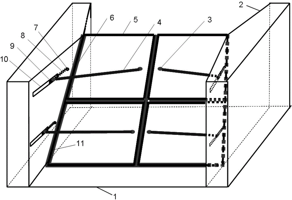
[0021] Such as figure 1 As shown, the pier is a concrete structure arranged symmetrically on both sides, or a reinforced concrete structure, or a masonry structure, etc., depending on the depth of the upstream water, based on ensuring safety and stability, the height of the pier should be greater than the depth of the upstream water to ensure Safe operation is the basis; the gate floor is reinforced concrete structure, or concrete structure, or masonry structure, etc., depending on the depth of the upstream water, based on ensuring safety and stability; gate piers and gate floors on both sides are poured on site, and poured Form a complete overall structure to increase its stability; the self-weight water depth of the gate is determined to ensure that it can be opened and closed freely and ensure safe operation under the upstream water pressure and the traction force of the traction spring; the space inclined axis adopts Cast steel, alloy and other metal materials are fixed on...


PUM


Abstract

The invention relates to a connecting rod spring trail-type double-deck bi-parting spatial tilting shaft waterpower self-control gate. The gate comprises gate piers and a gate chamber. The gate further comprises double-deck bi-parting gate bodies, spatial tilting shafts and a vibration damping and traction device. Two sections of the upper spatial tilting shaft and the lower spatial tilting shaft are symmetrically arranged on the gate piers arranged on two sides. The vibration damping and traction device is arranged between the downstream face of the gate bodies and the gate piers. The vibration damping and traction device comprises connecting rods, sliding blocks, sliding rails and traction springs, wherein one end of each connecting rod is fixed in the middle, close to the inner side edge, of the corresponding gate body, and the other end of each connecting rod is connecting with the corresponding sliding block through a universal hinge. The sliding rails are arranged on the downstream sides of the gate piers. The sliding blocks are movably installed in the sliding rails. One end of each traction spring is fixed to the corresponding gate pier through a spring base, and the other end of each traction spring is connected with the corresponding sliding block. According to the connecting rod spring trail-type double-deck bi-parting spatial tilting shaft waterpower self-control gate, the opening angle of the gate can be better reduced timely along with the falling of the water level, and the aims of automatic water storage and water drainage are better achieved.

Description

[0001] 1. Field [0002] The invention relates to a connecting rod spring traction type double-layer split space oblique axis hydraulic automatic control gate. 2. Background technology [0003] The hydraulic automatic flap gate is an energy-saving and environmentally friendly gate, which has been widely used in my country, but there are: complex hydraulic characteristics, huge water flow resistance caused by the gate plate and its supporting structure, and the huge pressure of the water flow , There will be problems such as "slapping" damage phenomenon, inflexible opening and closing during operation. For this reason, the oblique-axis hydraulic automatic control gate and so on have been developed. [0004] The oblique axis hydraulic self-control gate can automatically fulfill the requirements of the gate for water storage and discharge, and can replace hydraulic automatic flap gates, conventional gates, masonry barrages, rubber dams and other facilities for water storage and d...

Claims


Application Information

Patent Timeline
IPC IPC(8): E02B7/48
Inventor 王春堂王世龑
Owner SHANDONG AGRICULTURAL UNIVERSITY
Learn More