
Rotary gate automatically controlled by waterpower and provided with horizontal shaft

A hydraulic automatic control and gate technology, which is applied in water conservancy projects, sea area engineering, coastline protection, etc., can solve the problems of complex hydraulic characteristics of hydraulic automatic flap gates, large force on gate plates and gate piers, unfavorable gate stability, etc.

Inactive Publication Date: 2015-10-21
SHANDONG AGRICULTURAL UNIVERSITY
View PDF8 Cites 4 Cited by
  • Summary
  • Abstract
  • Description
  • Claims
  • Application Information

AI Technical Summary

Problems solved by technology

But there are still some deficiencies: ①The hydraulic characteristics of the hydraulic automatic flap gate are relatively complicated; ②The supporting structure of the gate is the horizontal axis hydraulic automatic flap gate behind the door.
Since the horizontal shaft is set in the middle of the gate, the gate above the shaft fold and the gate below the shaft are simultaneously subjected to upstream water pressure, and sufficient force is required to turn the gate plate over, resulting in too much force on the gate plate and the gate pier, which is not conducive to the gate’s smooth movement. Stablize
③The entire ram and its supporting structure are in the middle of the water flow, which creates a huge resistance and seriously affects the ability of the water flow to drain
④Hydraulic automatic flap gates will periodically slap back and forth on the pier or dam sill during operation, which is extremely destructive
⑤ When the hydraulic automatic flap gate is opened, it requires a sufficiently high water level before it can be opened; when it is closed, it requires a sufficiently low water level upstream of the door panel to close, which will affect the normal water storage
⑥Due to the characteristics of the support structure of the automatic flap gate, the opening of the gate is limited, and some of them either do not open, or open to the maximum at once, and cannot be automatically adjusted at any time with the change of the upstream water flow, etc.

Method used


Image

  • Rotary gate automatically controlled by waterpower and provided with horizontal shaft
  • Rotary gate automatically controlled by waterpower and provided with horizontal shaft

Examples


Embodiment Construction

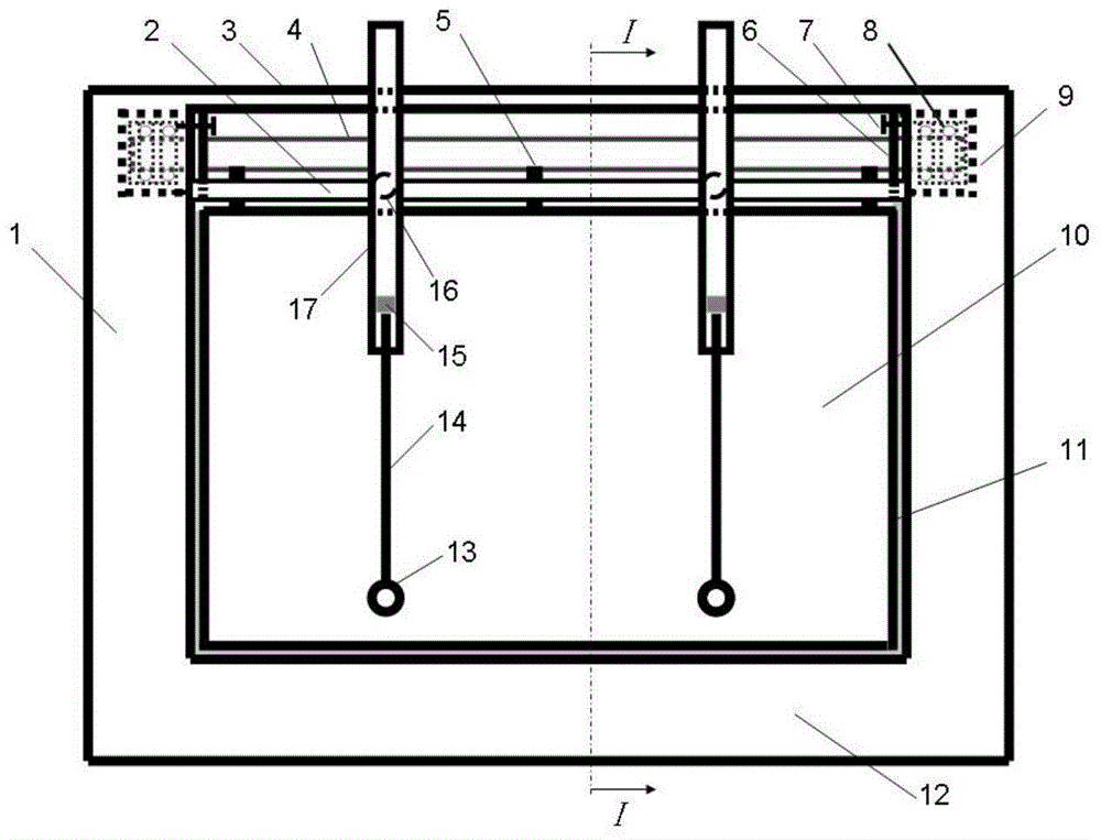
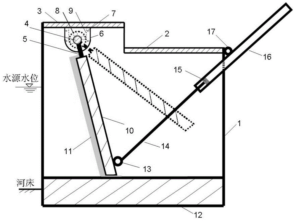
[0015] Such as figure 1 , figure 2 As shown, the device mainly includes a lock chamber, a bearing body, a gate shaft, a rotary gate, a suspension mechanism, a cover bridge, a working bridge, a water stop, and a hydraulic damping device.

[0016] The gate pier is a symmetrically arranged concrete structure, or reinforced concrete structure, or masonry structure, etc. on both sides. Depending on the upstream water depth and force, the height of the gate pier should be greater than the upstream water depth to ensure safety. It is based on operation; the gate bottom plate is reinforced concrete structure, or concrete structure, or mortar masonry structure, etc., depending on the upstream water depth, force, and safety and stability requirements; gate piers and gate bottom plates on both sides are poured on site, and poured into A complete overall structure to increase its stability; the revolving gate is a prefabricated reinforced concrete structure or other materials with certa...


PUM


Abstract

The invention relates to a rotary gate automatically controlled by waterpower and provided with a horizontal shaft. The rotary gate comprises a lock chamber, bearing bodies, a gate shaft, a rotary gate body, suspension mechanisms, a cover plate bridge, a service bridge, a water-stopping unit and hydraulic vibration-damping units. Each bearing body is composed of a bearing groove, a bearing, a bearing gland and a bolt; the gate shaft is fixed in the bearing grooves through the bearings; the upper end of the rotary gate body is installed on the gate shaft through the suspension mechanisms; each hydraulic vibration-damping unit is composed of a piston cylinder, a piston and a piston rod; and each piston cylinder is connected to the service bridge at the side in the downstream direction through a bridge hinge, and each piston rod is connected to the lower end of the rotary gate body through a gate hinge. According to the invention, the state of water flow in the lock chamber is stable, the water storage and discharge capacity can be improved, the automatic opening and closing of the rotary gate can be controlled completely by means of the condition of upland water, the opening degree of the rotary gate can be automatically adjusted at any moment along with the water level change, and the problem of siltation in front of the gate can be solved.

Description

[0001] 1. Field [0002] The invention relates to a horizontal axis hydraulic automatic control rotary gate. 2. Background technology [0003] The hydraulic automatic flap gate is an energy-saving and environment-friendly gate developed by Chinese water conservancy science and technology workers and has completely independent intellectual property rights. Since the birth of the first generation of hydraulic automatic flap gates in the early 1960s, it has experienced four development stages: horizontal axis double hinge type, multi hinge type, roller connecting rod type and slider type hydraulic automatic control type. But there are still some deficiencies: ① the hydraulic characteristics of the hydraulic automatic flap gate are relatively complicated; ② the supporting structure of the gate is the horizontal axis hydraulic automatic flap gate behind the door. Since the horizontal shaft is set in the middle of the gate, the gate above the shaft fold and the gate below the shaft...

Claims


Application Information

Patent Timeline
IPC IPC(8): E02B7/40E02B7/54
Inventor 王春堂王世龑
Owner SHANDONG AGRICULTURAL UNIVERSITY
Learn More