
Hydro-automatic hollow flap gate

A flap gate, hydraulic automatic control technology, applied in water conservancy projects, marine engineering, coastline protection and other directions, can solve the problem of inflexible opening, non-opening, opening to the maximum if necessary, affecting the ability to pass water, etc.

Inactive Publication Date: 2015-03-25
SHANDONG AGRICULTURAL UNIVERSITY
View PDF4 Cites 12 Cited by
  • Summary
  • Abstract
  • Description
  • Claims
  • Application Information

AI Technical Summary

Problems solved by technology

However, there are still many defects in the hydraulic automatic flap gate: the horizontal axis type automatic flap gate requires a large enough water level when it is opened, that is, the water pressure to be generated on the door plate on the upper part of the horizontal axis must overcome the dead weight of the door plate and the pressure of the door plate. The water pressure generated at the lower part of the horizontal axis can only be opened, which greatly restricts the opening of the gate, and the opening is inflexible; when closing, it requires a sufficiently low water level upstream of the door panel to close, which will affect the normal water storage; due to the horizontal axis Due to the characteristics of the support structure of the type automatic flap gate, the opening of the gate is limited, and some of them either do not open, or open to the maximum at once, and cannot be automatically adjusted at any time with the change of the upstream water volume; moreover, currently The supporting structure of the hydraulic automatic flap gate is in the water flow, which affects the water passing capacity

Method used


Image

  • Hydro-automatic hollow flap gate
  • Hydro-automatic hollow flap gate

Examples


Embodiment Construction

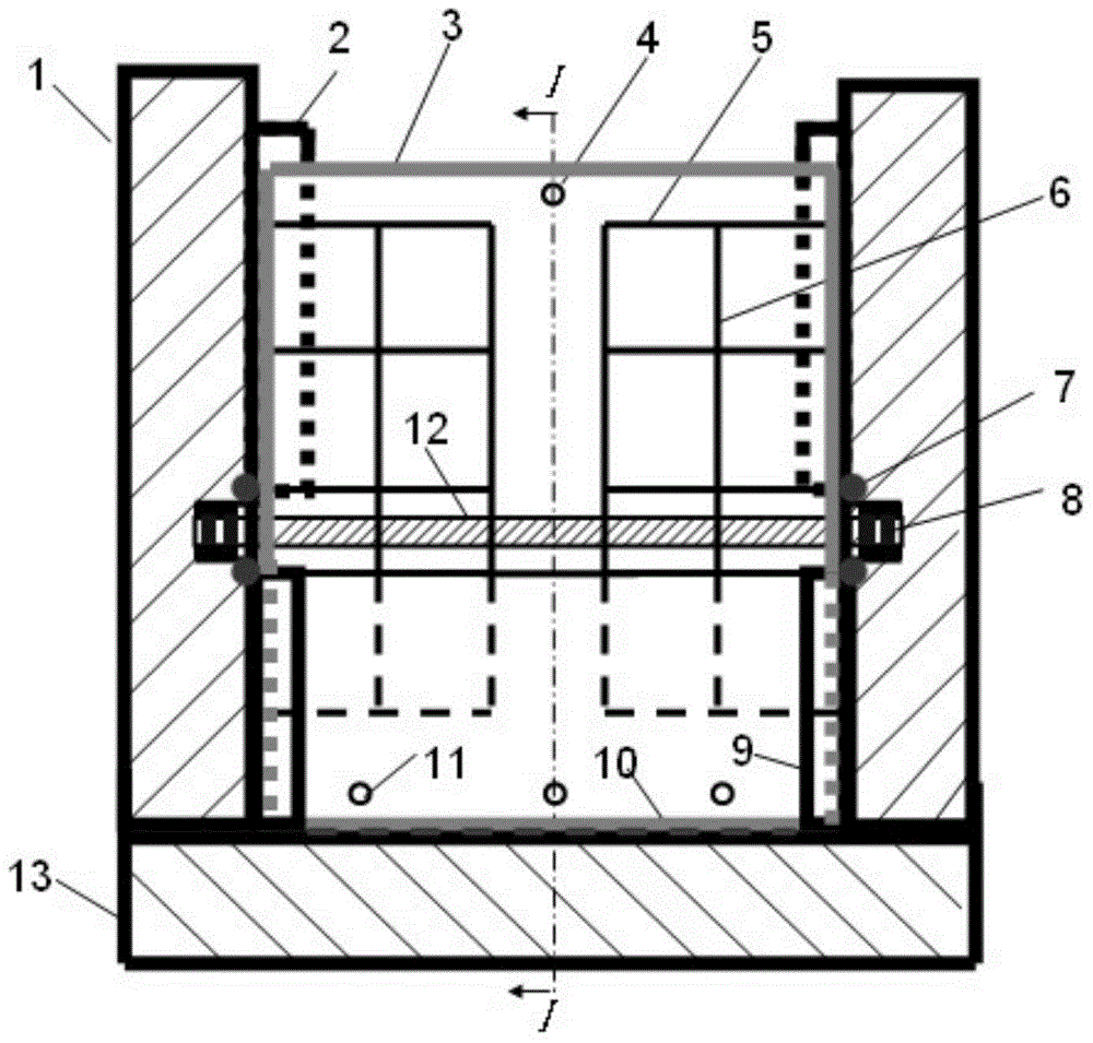
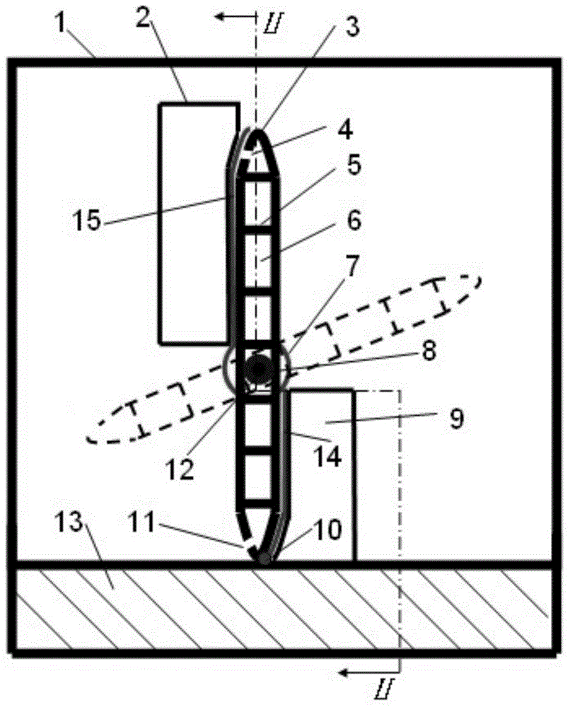
[0012] The pier is of concrete structure, or reinforced concrete structure, or masonry structure, etc., based on the ability to ensure the safety of the pier; the bottom plate of the gate is of reinforced concrete structure, or concrete structure, or masonry structure, etc. The basis is to ensure the safety of the gate pier; the gate piers on both sides and the gate floor are poured on site, and poured into a complete overall structure to increase its stability; the height of the gate pier should be greater than or equal to the height of the gate to ensure safe operation. The gate shaft is made of stainless steel or alloy and is fixed on the gate pier through bearings. The gate shaft is required to have sufficient strength and rigidity to ensure that the gate shaft does not produce any deformation; the hollow gate is made of cast steel or alloy steel and should have Certain rigidity and strength, anti-rust treatment, the hollow gate is provided with longitudinal and transverse ...


PUM


Abstract

The invention relates to a hydro-automatic hollow flap gate which comprises gate piers, a gate bottom plate, an upper stop dog, an upper stop dog water stop, a hollow gate body, a water / gas drainage hole, O-shaped water stop rings, a bearing, a lower stop dog, a lower stop dog water stop, a gate bottom water stop, water inlet holes, a gate shaft and the like. The gate piers are symmetrically arranged on the two sides of the gate bottom plate. The upper stop dog and the lower stop dog are arranged on the upper portion and the lower portion of the corresponding gate pier on one side of the upstream portion of the hollow gate body respectively. The hollow gate body is fixed between the two gate piers through the gate shaft. The upper portion of the hollow gate body is provided with the water / gas drainage hole and the water inlet holes. According to the hydro-automatic hollow flap gate, the opening of the hollow gate body can be automatically adjusted at any time along with the change of the water inflow from the upstream portion, the gradually opening performance of the hollow gate body is good, more labor is saved in the opening and closing processes, and meanwhile, the hollow gate body is provided with the maximum discharging ability. The hydro-automatic hollow flap gate is free of external force, the hollow gate is automatically opened and closed by totally depending on the water from the upsteeam portion, and application and popularization in practice are facilitated.

Description

[0001] 1. Fields: [0002] The invention relates to a hydraulic automatic control hollow flap gate. 2. Background technology [0003] The hydraulic automatic flap gate is a kind of energy-saving and environment-friendly gate developed by Chinese water conservancy engineering technicians after more than 40 years of hard work and has completely independent intellectual property rights. Since the birth of the first generation of hydraulic self-controlled flap gates in the early 1960s, it has experienced four development stages: horizontal axis double hinge type, multi-branch hinge type, roller linkage type and slider type hydraulic automatic control type. [0004] The main structure of the hydraulic automatic flap gate is a solid gate of reinforced concrete or other materials, which can generally be used to replace flat lift gates, arc gates and rubber dams, and is suitable for river water storage and flood discharge. However, there are still many defects in the hydraulic automa...

Claims


Application Information

Patent Timeline
IPC IPC(8): E02B7/46E02B7/54
CPCE02B7/46E02B7/54
Inventor 王春堂王世龑
Owner SHANDONG AGRICULTURAL UNIVERSITY
Learn More