Oblique-shaft type hydraulic self-control gate

A hydraulic automatic control and gate technology, which is applied in water conservancy projects, marine engineering, coastline protection, etc., can solve the problems of gate opening limit, affecting normal water storage, and inflexible opening.

Active Publication Date: 2015-01-07
SHANDONG AGRICULTURAL UNIVERSITY
View PDF4 Cites 10 Cited by
  • Summary
  • Abstract
  • Description
  • Claims
  • Application Information

AI Technical Summary

Problems solved by technology

During the opening process of the horizontal axis automatic flap gate, the gate above the transverse support structure rotates around the transverse support structure along the direction of water flow, while the gate below the transverse support structure rotates around the transverse support structure against the direction of water flow. Enough force is required to turn the gate over, and the force on the gate and the gate pier is too large, which is not conducive to the stability of the gate.
[0007] Thirdly, during the discharge process of the horizontal-axis automatic flap gate, part of the water flows downstream from the water passage between the top and both sides of the gate plate and the gate pier, and part of the water flows from the bottom of the gate plate to the bottom plate and both sides of the gate plate. The water passage between the piers flows downstream, that is to say, the entire ram is in the flow of water that is being discharged. For the discharge, the ram creates a huge resistance and seriously disturbs the state of the water flow. , which seriously affects the discharge capacity of the water flow, especially during the flood period, which will seriously affect the flood discharge
[0008] F

Method used


Image

  • Oblique-shaft type hydraulic self-control gate
  • Oblique-shaft type hydraulic self-control gate

Examples


Embodiment Construction

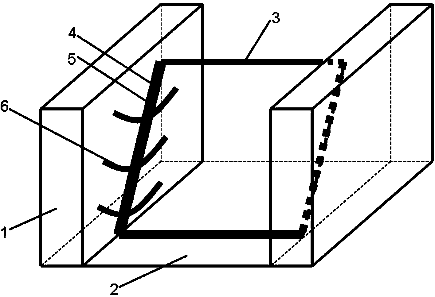
[0022] Such as figure 1 As shown, this device mainly includes gate pier, gate bottom plate, gate plate, water stop, inclined shaft and circular arc hydraulic vibration damping device.

[0023] Pier 1 is a symmetrically arranged concrete structure, or reinforced concrete structure, or mortar and masonry structure with upright on both sides, depending on the upstream water depth. The height of the pier should be greater than the upstream water depth to ensure safe operation; 2 It is a reinforced concrete structure, or a concrete structure, or a mortar-masonry structure, etc., depending on the size of the upstream water depth; the gate piers and gate bottom plates on both sides are poured on-site and poured into a complete overall structure to increase its stability; Gate 3 is a prefabricated reinforced concrete structure or other materials with certain rigidity and strength. The gate texture is required to be uniform. The weight of the gate is determined according to the water sto...


PUM


Abstract

The invention relates to an oblique-shaft type hydraulic self-control gate comprising gate piers, a gate floor plate, a gate plate, a waterstop, an oblique shaft and arc hydraulic damping devices. The gate piers are symmetrically and vertically disposed on two sides of the gate floor plate, and the oblique shaft is disposed on the gate pier on one side and is in rigid connection with the gate pier through an anchoring structure; the lower end of the oblique shaft is fixed at the joint of the gate pier on the side and the gate floor plate, and the upper end of the oblique shaft faces the upstream direction of water flow, and the oblique shaft is mounted obliquely with a 45-degree angle formed between the oblique shaft and the bottom edge of the gate pier of the side; the gate is fixed on the oblique shaft, and the arc hydraulic damping devices are arranged between the gate and one gate pier. By the oblique-shaft type hydraulic self-control gate, opening and closing of the gate can be controlled automatically according to the upstream water level, automatic control of the gate through upstream coming water is realized, a working system of unattended operation is realized, and popularization and application in practice are facilitated.

Description

[0001] 1. Field [0002] The invention relates to an inclined axis hydraulic automatic control gate. 2. Background technology [0003] The hydraulic automatic control flap gate is a kind of hydraulic gate, which is an energy-saving and environmentally-friendly gate developed by our country's hydraulic engineering technicians after more than 40 years of hard work and has completely independent intellectual property rights. Since the birth of the first generation of hydraulic automatic flap gates in the early 1960s, it has experienced four development stages of horizontal axis double hinge type, multiple hinge type, roller link type and slider type hydraulic automatic control type. [0004] The main structure of the hydraulic automatic flap gate is reinforced concrete, which can generally be used to replace flat hoist gates, arc gates and rubber dams, and is suitable for river water retention and flood discharge. Because the hydraulic automatic flap gate has a relatively simple struct...

Claims


Application Information

Patent Timeline
IPC IPC(8): E02B7/46
CPCE02B7/46
Inventor 王春堂侯世文王世龑
Owner SHANDONG AGRICULTURAL UNIVERSITY
Why Eureka
Try Eureka