
Speed reducer and shell thereof

A reducer and shell technology, which is applied in the field of reducer shells, can solve the problems of irreconcilable lubrication and efficiency, uncontrollable, high oil churning loss, etc., achieve stable and balanced lubrication effect, improve efficiency, and improve work efficiency Effect

Active Publication Date: 2015-12-23
BEIJING ELECTRIC VEHICLE
View PDF6 Cites 3 Cited by
  • Summary
  • Abstract
  • Description
  • Claims
  • Application Information

AI Technical Summary

Problems solved by technology

At present, the oil churning loss of gears can be reduced by adjusting lubricating oil parameters and controlling the amount of oil injected. However, when the vehicle is running due to changes in the pitch angle of the ramp, and the same product is arranged at different angles on different models, the lubrication and efficiency cannot be reconciled. If the situation is too high, the height of the lubricating oil level will change, and it is uncontrollable, and the oil churning loss will be too high

Method used


Image

  • Speed reducer and shell thereof
  • Speed reducer and shell thereof
  • Speed reducer and shell thereof

Examples


Embodiment Construction

[0031] Embodiments of the invention are described in detail below, examples of which are illustrated in the accompanying drawings. The embodiments described below by referring to the figures are exemplary and are intended to explain the present invention and should not be construed as limiting the present invention.

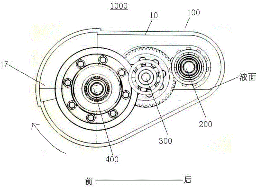
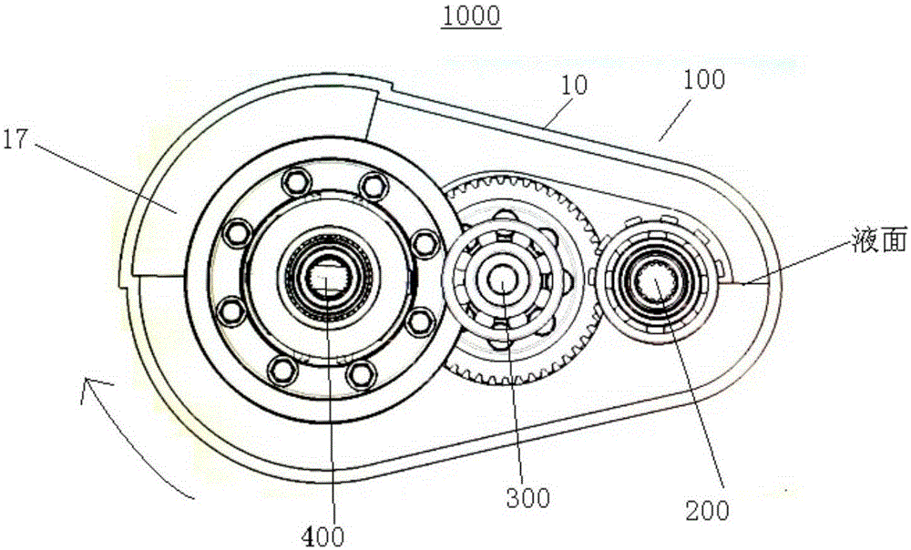
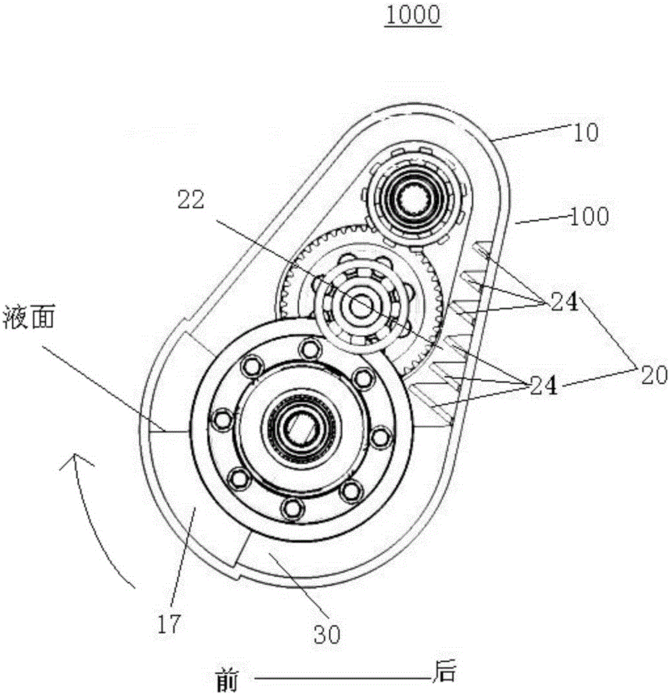
[0032] The housing 100 of the speed reducer 1000 according to the embodiment of the present invention will be described in detail below with reference to the accompanying drawings.

[0033] The housing 100 of the speed reducer 1000 according to the embodiment of the present invention may include: a housing body 10 and an isolation device 20 . Such as Figure 4 As shown, there is a cavity in the housing body 10, and the housing body 10 is provided with output shaft holes 11, intermediate shaft holes 12 and Input shaft hole 13.

[0034] According to an embodiment of the present invention, the housing body 10 may include: a first housing 14 and a second housing, ...


PUM


Abstract

The invention discloses a speed reducer and a shell thereof. The shell of the speed reducer comprises a shell body and an isolating device. The shell body is provided with a cavity. An output shaft hole, an intermediate shaft hole and an input shaft hole which are sequentially arranged from the front portion of the shell body to the rear portion of the shell body are formed in the shell body. The isolating device is arranged below the intermediate shaft hole and / or the input shaft hole, so that a dynamic oil storage area is formed in the cavity. The dynamic oil storage area is provided with a circulating oil inlet end and a circulating oil outlet end. The circulating oil inlet end and the circulating oil outlet end are communicated with the cavity, and the circulating oil inlet end is located above the circulating oil outlet end. At least part of the area, located in front of the isolating device, of the cavity is a static oil storage area. By arranging the isolating device, oil stirring loss of the speed reducer can be reduced, and the working efficiency of the speed reducer can be improved.

Description

technical field [0001] The invention relates to the technical field of speed reducers for vehicles, in particular to a casing of a speed reducer and a speed reducer with the casing. Background technique [0002] Driving range is an important evaluation index of electric vehicles. Simply increasing the power to increase driving range is not conducive to vehicle cost control, and will also lead to bottlenecks in the layout of battery space. Therefore, it has become an urgent problem to be solved by improving the efficiency of the whole vehicle system to extend the mileage of the vehicle and reduce the cost of the whole vehicle. [0003] The transmission efficiency of the reducer is an important link in the efficiency of the vehicle system. The efficiency loss of the reducer mainly comes from gear meshing friction, bearing friction, and oil churning loss. At present, the oil churning loss of gears can be reduced by adjusting lubricating oil parameters and controlling the amoun...

Claims


Application Information

Patent Timeline
Patent Type & Authority Applications(China)
IPC IPC(8): F16H57/02F16H57/021F16H57/023F16H57/04
CPCF16H57/02F16H57/021F16H57/023F16H57/045F16H57/0453F16H2057/02043
Inventor 李迎宏贾秀峰
Owner BEIJING ELECTRIC VEHICLE
Learn More