Roller type force balancing unit pump

A force-balanced, roller-type technology, applied in the field of hydraulic plunger pumps, can solve problems such as processing, use, and maintenance requirements and high costs, affecting service life and durability, and rapid rise in cylinder temperature, so as to enhance the reliability of movement performance, improve mechanical efficiency, and reduce mechanical vibration

Pending Publication Date: 2020-08-07
ZHEJIANG UNIV OF TECH
View PDF1 Cites 1 Cited by
  • Summary
  • Abstract
  • Description
  • Claims
  • Application Information

AI Technical Summary

Problems solved by technology

However, the traditional plunger pump has problems such as low efficiency, large vibration, high noise, and low life due to the limitations of friction pairs and size, and it is difficult to achieve the goal of high speed and high pressure.
[0003] The traditional one is the axial piston pump, which has many relatively moving parts inside, has high requirements for material and machining accuracy, is sensitive to oil pollution, has high requirements and costs for processing, use, and maintenance, and is expensive; Rotating with the transmission shaft, the moment of inertia is large, resulting in slow response to start, stop, and speed regulation, which is not conducive to controlling the output flow of the pump through speed regulation; there are many friction pairs in the cylinder, and the temperature of the cylinder will rise under high-speed rotation Faster, the wear of the valve plate, plunger and other parts directly affects the service life and durability of the pump
In addition, due to the limitation of the working principle of the plunger pump itself, each plunger can only achieve one oil suction and one oil discharge when the transmission shaft rotates one revolution, and its displacement is limited.

Method used


Image

  • Roller type force balancing unit pump
  • Roller type force balancing unit pump
  • Roller type force balancing unit pump

Examples


Embodiment Construction

[0035] The present invention will be further described below in conjunction with the accompanying drawings.

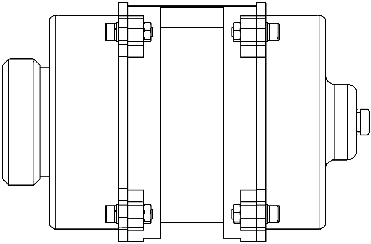
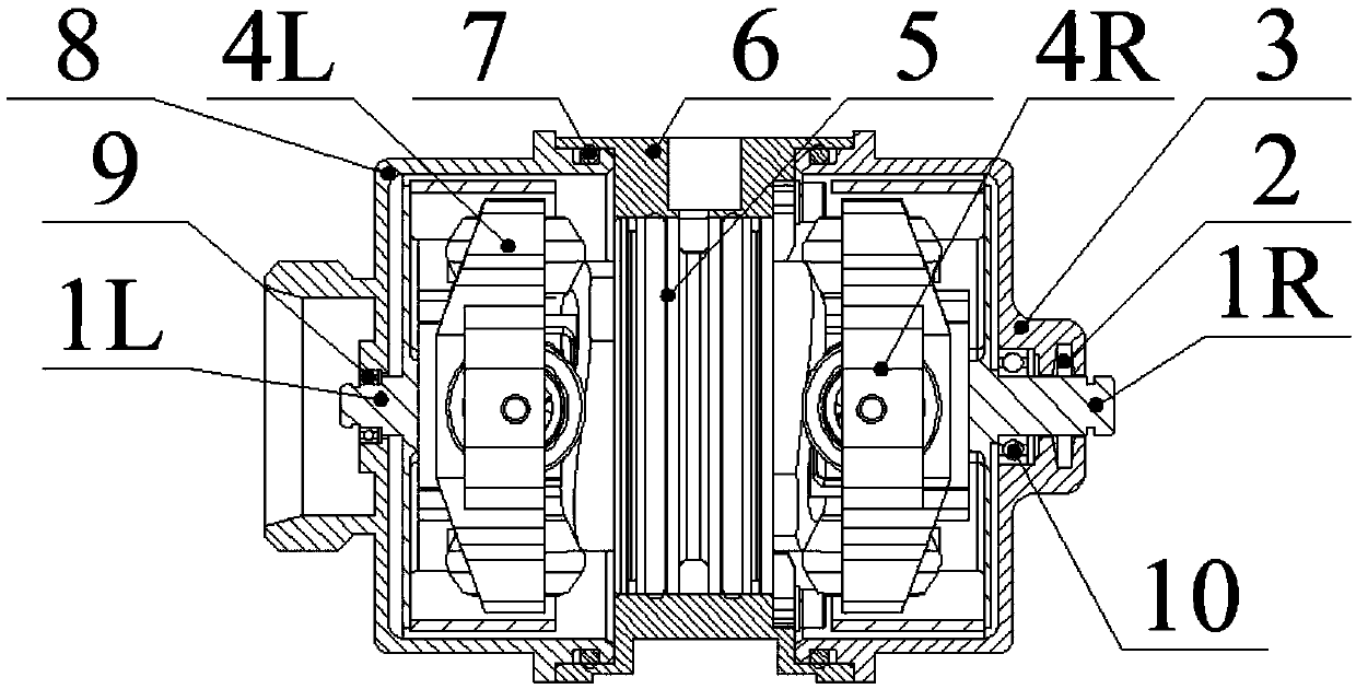
[0036] The roller-type force-balanced unit pump of the present invention includes: a right coupling assembly 1R, a right end cover 3, a left roller assembly 4L and a right roller assembly 4R, a pump core assembly 5, a pump casing 6, a left end cover 8, and a left coupling 1L . The right end cover 3 is connected to the right end surface of the pump casing 6 through bolts, and the left end cover 8 is fastened to the left end surface of the pump casing 6 through bolts. The sealing between the right end cover 3 and the pump casing 6 and the left end cover 8 and the pump casing 6 mainly depends on the sealing ring 7 . The right coupling 1R ensures the axial positioning with the right end cover 3 through the rolling ball bearing 10, and through the rolling ball bearing 10, the movement isolation between the right coupling 1R and the right end cover 3 is realized, and the ri...


PUM


Abstract

Disclosed is a roller type force balancing unit pump. A rolling bearing is mounted between a right coupling and a right roller assembly. Left and right cams are symmetrically distributed on both sidesof a pump core assembly with the phase difference of 90 DEG. A roller assembly rolls on the cam surfaces. Four conical rollers are distributed on the single side. Every two conical rollers are fixedto a C-shaped roller support as a group through a pin shaft. A copper sleeve of a pump core assembly and a cylinder body are respectively provided with two pairs of rectangular high pressure and low pressure oil holes uniformly distributed in the circumferential direction. The rectangular high pressure and low pressure oil holes correspondingly make contact with first and second flow distributiongrooves in the upper portions of a piston to suck and discharge oil. The cylinder body is provided with an annular oil groove communicating with the high-pressure oil holes, and oil liquid flowing outof the two high-pressure oil holes is collected together. The mass of a rotor which is composed of a first roller support assembly, a third roller support assembly, a transmission shaft and left andright concentric rings should be equal to the sum of the mass of a rotor which is composed of a second roller set, a fourth roller support assembly and the piston. First high pressure and low pressurecavities in a pump core communicate with the first flow distribution groove of the piston all the time. Second high pressure and low pressure cavities communicate with the second flow distribution groove of the piston all the time.

Description

technical field [0001] The invention relates to a hydraulic plunger pump, belonging to hydraulic pumps and hydraulic motors in the field of fluid transmission and control. Background technique [0002] As the power component of the hydraulic system, the hydraulic pump can transfer the mechanical energy of the prime mover or other external energy to the liquid, increase the energy of the liquid, and is widely used in construction machinery and aerospace. However, due to the limitation of friction pair and size, the traditional plunger pump has problems such as low efficiency, large vibration, high noise, and low service life, and it is difficult to achieve the goal of high speed and high pressure. [0003] The traditional one is the axial piston pump, which has many relatively moving parts inside, has high requirements for material and machining accuracy, is sensitive to oil pollution, has high requirements and costs for processing, use, and maintenance, and is expensive; Ro...

Claims


Application Information

Patent Timeline
Patent Type & Authority Applications(China)
IPC IPC(8): F04B19/20F04B9/02F04B53/00F04B53/14
CPCF04B9/02F04B19/20F04B53/00F04B53/14
Inventor 阮健钱家圆童成伟黄煜申屠胜男孟彬
Owner ZHEJIANG UNIV OF TECH
Why Eureka
Try Eureka