Supply system, in particular for gear mechanisms and generators
A technology of supply system and transmission mechanism, applied in the direction of engine lubrication, engine, wind power generation, etc., to achieve the effect of high flexibility
Inactive Publication Date: 2016-03-23
ROBERT BOSCH GMBH
View PDF7 Cites 1 Cited by
- Summary
- Abstract
- Description
- Claims
- Application Information
AI Technical Summary
Problems solved by technology
[0009] The disadvantage is that in this case the vacuum generator has to be integrated in the lubrication system
Method used
View moreImage
Smart ImageViewing Examples
Examples
no. 1 approach
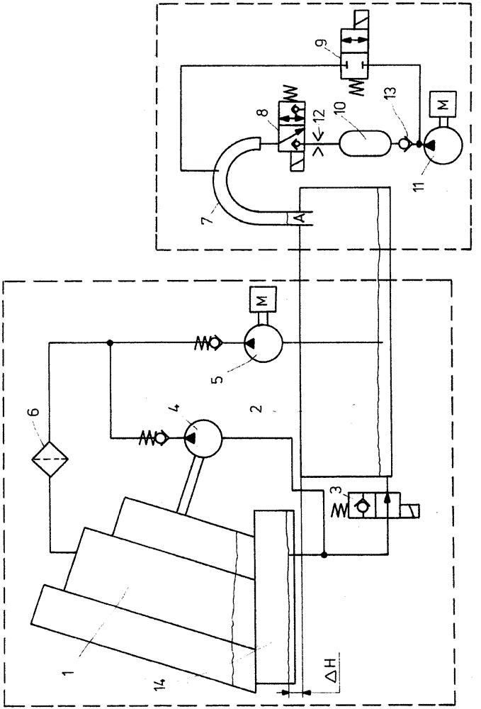
[0054] Optionally, the possibility is also provided that the hydraulic delivery device is supplemented by an electric motor-pump unit like 5 . For emergency lubrication in the event of a power failure, it is therefore equipped with an electrical memory unit.
Login to View More PUM
 Abstract
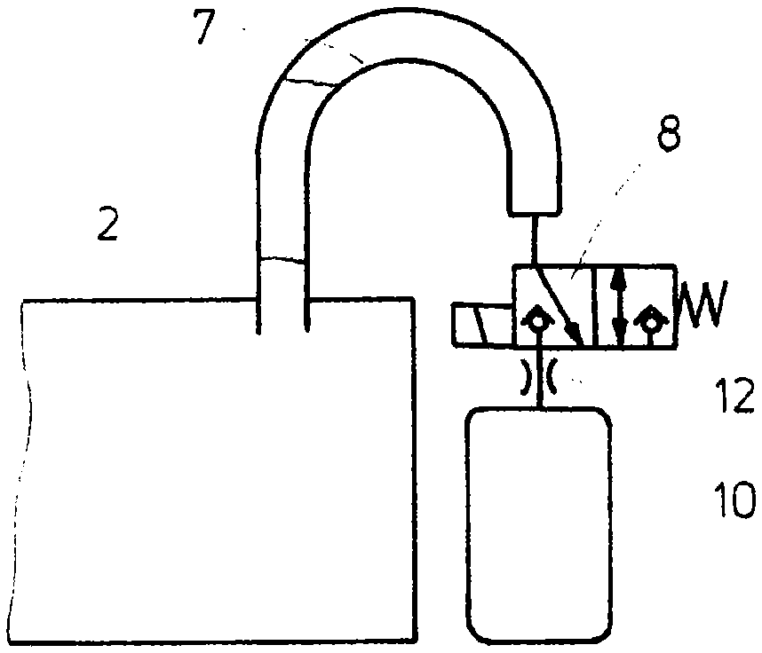
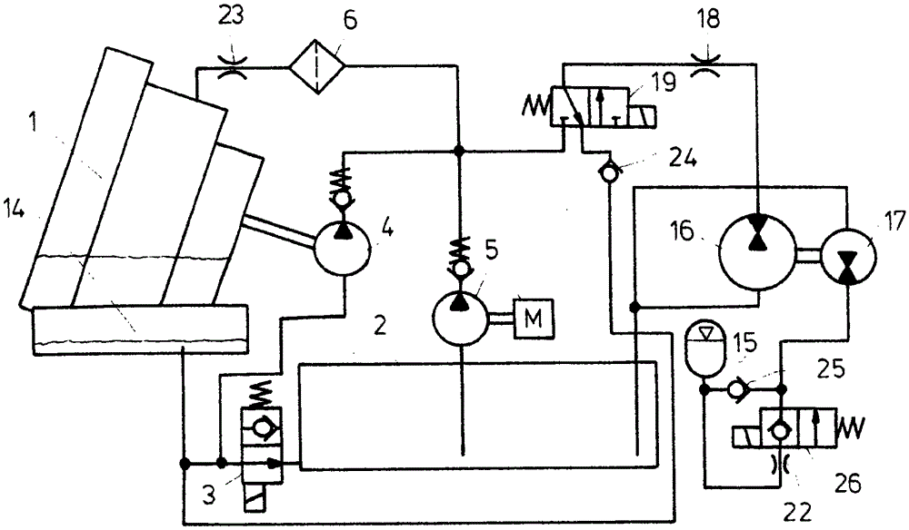
A lubricating system has been disclosed for gear mechanisms (1) or generators, in particular for gear mechanisms (1) of wind power plants, which lubricating system permits a switchover between dry sump lubrication and wet sump lubrication. This takes place by way of a delivery device which increases the pressure in a lubricant tank (2) selectively or in an emergency, for example a power outage, and presses a lubricant back into an oil sump (14) in the gear mechanism (1), whereupon a lubricant level is increased there and wet sump lubrication is realized. The delivery device can have a compressor (11). Said compressor (11) can charge a pressure accumulator (10) via a non-return valve (9) or can increase the pressure in the lubricant tank (2) directly (not shown here). The delivery device can consist of hydraulic, pneumatic or else electrical components. If it is pneumatic, it can be separated from the hydraulic lubricating system via an elbow (7).
Description
technical field [0001] The invention relates to a supply system for coolant and / or lubricant, in particular for transmissions and generators. Background technique [0002] Drive trains are among the most heavily loaded components of large plants, especially wind power plants. Transmissions must withstand enormous torques, vibrations and weather conditions. At the same time, the efficiency of the transmission mechanism should be as high as possible. [0003] For this reason, the demands placed on the structural components of the transmission also increase. In particular, for example, supply systems for cooling and / or lubricating materials are included. The supply system ensures the lubrication of the bearings and gears of the transmission. The lubrication system thus reduces wear and friction and increases the service life and loadability of the transmission components. [0004] The use of dry sump lubrication minimizes churning losses in the transmission during normal o...
Claims
Login to View More Application Information
Patent Timeline
 Patent Type & Authority Applications(China)
IPC IPC(8): F16H57/04F16N7/38
CPCF05B2260/98F16H57/0442F16H57/0447F16H57/0456F16H57/0457F16H57/0495F16N7/38F16N2260/20F03D80/70Y02E10/72F16H57/0435F16H57/0436F16H57/045
Inventor I·德尔托卢克K·乌尔里希B·施努尔M·奥佩尔特U·弗雷利希
Owner ROBERT BOSCH GMBH
Features
- R&D
- Intellectual Property
- Life Sciences
- Materials
- Tech Scout
- Unparalleled Data Quality
- Higher Quality Content
- 60% Fewer Hallucinations
Learn More Browse by: Latest US Patents, China's latest patents, Technical Efficacy Thesaurus, Application Domain, Technology Topic, Popular Technical Reports.
© 2025 PatSnap. All rights reserved.Legal|Privacy policy|Modern Slavery Act Transparency Statement|Sitemap|About US| Contact US: help@patsnap.com


