
Error-proof adjusting assembly of AMT clutch

A technology for adjusting components and clutches, applied to components with teeth, belts/chains/gears, mechanical equipment, etc., can solve the problems of AMT not running normally, clutches are easily damaged, etc., and achieve simple structure, reliable operation, and reduce errors. The effect of pretending probability

Inactive Publication Date: 2015-12-23
SHAANXI FAST GEAR CO
View PDF8 Cites 0 Cited by
  • Summary
  • Abstract
  • Description
  • Claims
  • Application Information

AI Technical Summary

Problems solved by technology

[0002] With the development of the economy and the improvement of transportation requirements, the AMT technology of heavy trucks is becoming more and more mature, and the market share of AMT is increasing year by year. Although AMT is improved based on traditional MT, some components are still different from MT; transmission or vehicle Assemblers are accustomed to assembling MTs, subject to inertial thinking and unfamiliar with assembly requirements, they often install the big end that should be installed on the end of the release fork to the end of the clutch actuator, because the end of the clutch actuator is a V-shaped groove with a semicircular bottom Therefore, when the assembly is wrong, the large head of the clutch adjustable push rod will be stuck on the V-shaped groove, resulting in problems such as AMT not operating normally and the clutch is easily damaged; according to statistics, the wrong installation of the clutch adjustment rod is the result of AMT assembly. The error with the highest probability and the most serious consequences

Method used


Image

  • Error-proof adjusting assembly of AMT clutch
  • Error-proof adjusting assembly of AMT clutch
  • Error-proof adjusting assembly of AMT clutch

Examples


Embodiment Construction

[0021] The present invention will be described in further detail below in conjunction with the accompanying drawings.

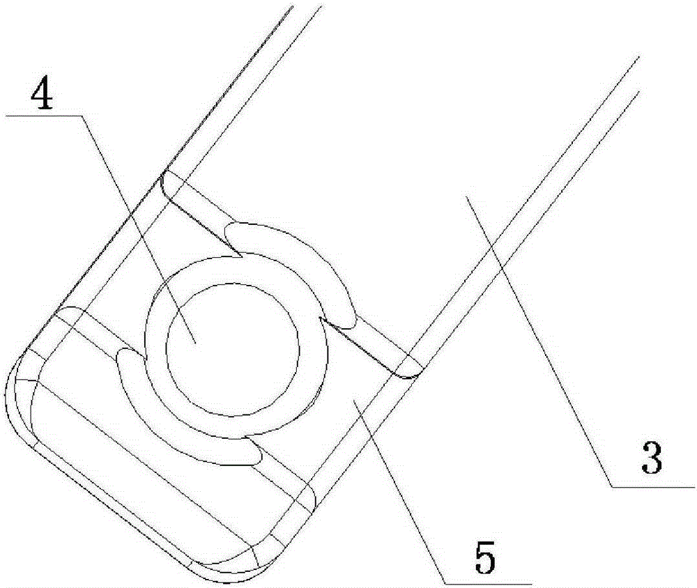
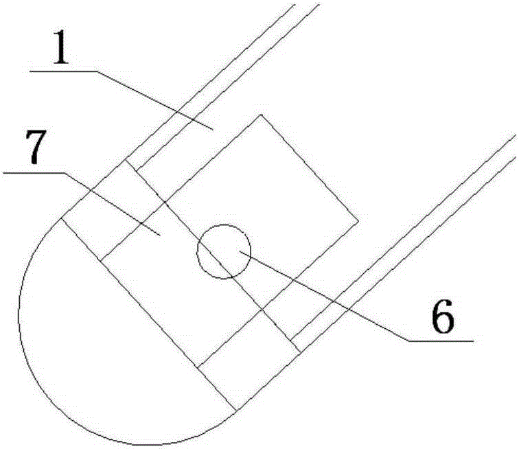
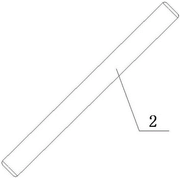
[0022] see Figure 1-5 The traditional clutch adjustable push rod structure includes a clutch push rod 11, a hex nut 12 and a clutch adjustment rod 13. Compared with the traditional clutch adjustable push rod structure, the present invention structurally includes a separation fork 3 and a separation push rod 1; separation A ball socket 4 for connecting the end of the separation push rod 1 is opened on the shift fork 3, and the surface of the separation shift fork 3 at the mouth of the ball socket 4 is processed with an arc-shaped groove 5; the separation push rod 1 is inserted into the bottom of the ball socket 4 for opening In the through hole 6 where the anti-error pin 2 is installed, the bottom of the separation push rod 1 is provided with a plane groove 7 at the position where the through hole 6 is processed, which is convenient for punching. The anti-er...


PUM


Abstract

The invention discloses an error-proof adjusting assembly of an AMT clutch. The error-proof adjusting assembly comprises a separation shifting fork and a separation push rod. A ball socket used for being connected with the end of the separation push rod is formed on the separation shifting fork, and an arc-shaped groove is processed in the surface, at an opening of the ball socket, of the separation shifting fork. A through hole for mounting of an error-proof pin is formed in the bottom, inserted in the ball socket, of the separation push rod in a penetrating manner. The error-proof pin is located in the arc-shaped groove, and the length of the error-proof pin is larger than the caliber of the ball socket. No error mounting happens to the end, inserted in the ball socket, of the separation push rod, and the situation that after the large end of the separation push rod is arranged, the ball socket is blocked, and consequently the separation push rod cannot move during use is avoided. The error-proof pin can do arc motion along the arc face through the arc-shaped groove, and the situation that motion interference happens to the error-proof pin and the separation shifting fork after the error-proof pin does axial motion is avoided. The error-proof adjusting assembly is simple in structure and reliable in work, through verification of actual work, the error mounting probability of the separation push rod of the AMT clutch can be greatly lowered, and operation error losses are reduced.

Description

technical field [0001] The invention relates to a transmission assembly, in particular to an AMT clutch anti-error adjustment assembly. Background technique [0002] With the development of the economy and the improvement of transportation requirements, the AMT technology of heavy trucks is becoming more and more mature, and the market share of AMT is increasing year by year. Although AMT is improved based on traditional MT, some components are still different from MT; transmission or vehicle Assemblers are accustomed to assembling MTs, subject to inertial thinking and unfamiliar with assembly requirements, they often install the big end that should be installed on the end of the release fork to the end of the clutch actuator, because the end of the clutch actuator is a V-shaped groove with a semicircular bottom Therefore, when the assembly is wrong, the large head of the clutch adjustable push rod will be stuck on the V-shaped groove, resulting in problems such as AMT not o...

Claims


Application Information

Patent Timeline
Patent Type & Authority Applications(China)
IPC IPC(8): F16H63/02
CPCF16H63/02
Inventor 冯瑞杨小辉赵丹
Owner SHAANXI FAST GEAR CO
Learn More