Two-degree-of-freedom decoupling reducing mechanism

A technology of deceleration mechanism and degree of freedom, applied in the direction of elastic suspension, control device, vehicle components, etc., can solve the problems of suspension limitation, large tire cornering stiffness, vertical acceleration and wheel dynamic load increase, and achieve convenient layout and installation , reduce the inertial force, the effect of small overall size

Active Publication Date: 2016-07-20
JILIN UNIV
View PDF5 Cites 5 Cited by
  • Summary
  • Abstract
  • Description
  • Claims
  • Application Information

AI Technical Summary

Problems solved by technology

However, the hub/wheel side drive system makes the unsprung mass of the suspension 2 to 3 times higher than that of traditional cars, which greatly increases the vertical acceleration of the body and the dynamic load of the wheels, and the ride comfort of the car is significantly worse.
At the same time, according to the theory of tire dynamics, when the average load is constant, the greater the dynamic load of the tire, the smaller the effective tire cornering stiffness, which is more unfavorable to the handling stability of the car.
Pat

Method used


Image

  • Two-degree-of-freedom decoupling reducing mechanism
  • Two-degree-of-freedom decoupling reducing mechanism
  • Two-degree-of-freedom decoupling reducing mechanism

Examples


Embodiment Construction

[0018] Below in conjunction with the implementation described in the accompanying drawings, further illustrate the specific content of the present invention and specific embodiments thereof:

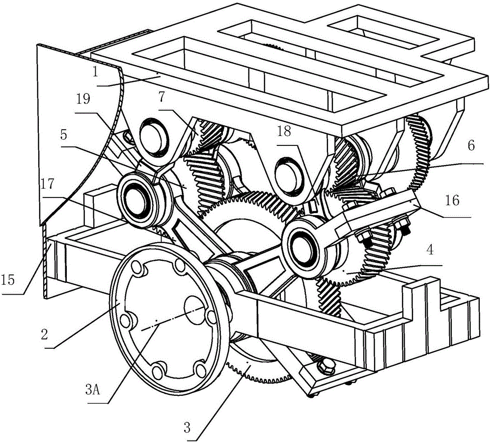
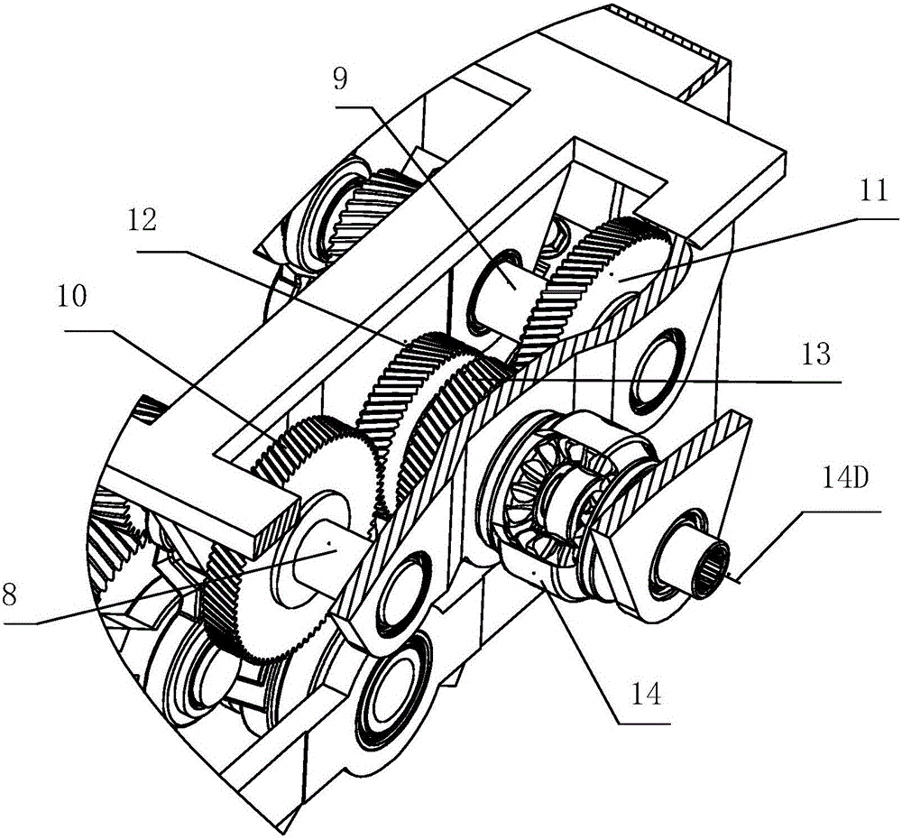
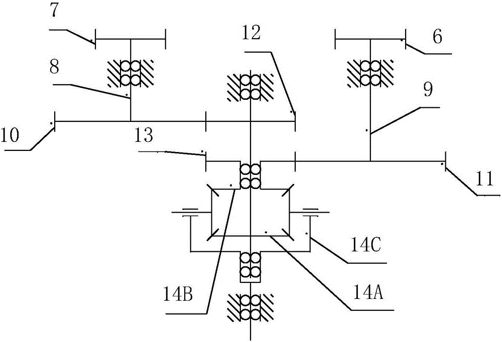
[0019] The realization of the decoupling function of the device provided by the present invention mainly depends on the connecting rod slider mechanism, the gear transmission mechanism and the differential mechanism, and mainly includes: the frame 1, the power output shaft 2, the power output wheel 3, the first idler wheel 4, II idler gear 5, I secondary reduction gear 6, II secondary reduction gear 7, I shaft 8, II shaft 9, I primary reduction gear 10, II primary reduction gear 11, I transfer wheel 12, Second transfer wheel 13, differential assembly 14, linear guide mechanism 15, first connecting rod bearing assembly 16, second connecting rod bearing assembly 17, third connecting rod bearing assembly 18, fourth connecting rod bearing assembly19.

[0020] The linear guide mechanism 15 c...


PUM


Abstract

The invention provides a two-degree-of-freedom decoupling reducing mechanism, and aims to solve the problem of contradiction between irregular forced vibration and stable driving force transmission at a power output end, and output stable power while reducing inertia force at the power output end. The two-degree-of-freedom decoupling reducing mechanism comprises a frame (1), a power output shaft (2), a power output wheel (3), idle wheels I and II (4, 5), secondary reduction gears I and II (6, 7), shafts I and II (8, 9), primary reduction gears I and II (10, 11), transfer gears I and II (12, 13), a differential assembly (14), a linear guide mechanism (15), and connecting rod bearing assemblies I, II, III and IV (16, 17, 18, 19). By adopting the two-degree-of-freedom decoupling reducing mechanism, decoupling of linear movement and rotation at the power output end can be realized, and a power source does not translate along with the power output end, so that the inertial force at the power output end is reduced, and stable output power is kept. The mechanism is small in overall size, is short in transmission chain, and is convenient to install and apply.

Description

technical field [0001] The invention belongs to the field of mechanical engineering, and in particular relates to a power transmission device for decoupling the degree of freedom of linear translation and the degree of freedom of fixed axis rotation. Background technique [0002] Distributed drive electric vehicles can achieve a variety of dynamic control, with good maneuverability and stability. At present, in the realization of the structure of distributed drive electric vehicles, the commonly used solution is that each wheel is equipped with a hub / wheel edge drive system. However, the hub / wheel side drive system makes the unsprung mass of the suspension 2 to 3 times higher than that of traditional cars, which greatly increases the vertical acceleration of the body and the dynamic load of the wheels, and the ride comfort of the car is significantly deteriorated. At the same time, according to the theory of tire dynamics, when the average load is constant, the greater the ...

Claims


Application Information

Patent Timeline
IPC IPC(8): B60G3/20B60K17/28B60K17/16B60K17/08
CPCB60G3/207B60K17/08B60K17/16B60K17/28
Inventor 田萌健高炳钊陈虹褚洪庆陶伟男
Owner JILIN UNIV
Why Eureka
Try Eureka