Linear electromagnetic valve

A solenoid valve and glyph technology, applied in the field of solenoid valves, can solve the problems of not being suitable for use in places with dense pipelines, occupying a small space, tubular battery valves, and high height of solenoid valve cores, and achieving simple and compact structure, simple installation, and easy installation. small space effect

Inactive Publication Date: 2015-12-23
刘海山
View PDF15 Cites 10 Cited by
  • Summary
  • Abstract
  • Description
  • Claims
  • Application Information

AI Technical Summary

Problems solved by technology

[0006] These types of solenoid valves require a special installation location to be fixed, and the inlet and outlet pipes must be properly arranged before they can be used. The height required for the installation of the solenoid valve core is relatively high, and it is not suitable for use in places with dense pipelines.
Moreover, when equipment transformation occurs and it is necessary to add solenoid valve control to the original gas path, the above-mentioned U-shaped and T-shaped solenoid valves need to re-arrange the direction of the gas path, and the cost is relatively high.
[0007] At present, there is no tubular battery valve on the market that can be directly connected to the existing gas circuit and occupies a very small space.

Method used


Image

  • Linear electromagnetic valve
  • Linear electromagnetic valve
  • Linear electromagnetic valve

Examples


Embodiment 1

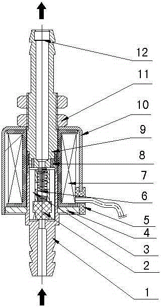
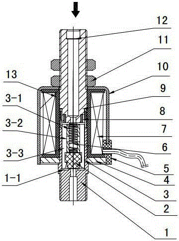
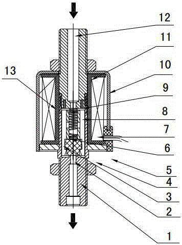
[0039] The trachea fixing part of Embodiment 1 adopts an external thread joint, the trachea fixing part of Embodiment 2 adopts an internal thread joint, and the trachea fixing part of Embodiment 2 adopts an intubation joint.

[0040] as shown in the picture As shown, Embodiment 4 to Embodiment 6 also adopted the above three matching methods respectively. The difference from the previous three embodiments is that it adopts the working mode of the reverse air circuit, the air intake is located in the air hole in the valve body, and the air outlet is the air hole in the static iron core.

[0041] Since the intake air directly acts on the bottom of the packing block, there is a tendency to push the packing block upwards. In order to achieve the sealing effect, the spring force of this type of solenoid valve is greater than that of the air intake on the static iron core.

[0042] The present invention maintains the air inlet, air outlet and other air passages on a straight line w...


PUM


Abstract

A linear electromagnetic valve comprises a valve body, a filler block, a movable iron core, a coil and a fixed iron core. A valve cavity used for containing the movable iron core is formed in the valve body. The coil is wound on a coil framework. The fixed iron core is fixedly connected with the coil framework. A coil housing is arranged outside the coil. The filler block is fixedly connected with the movable iron core. The movable iron core and the fixed iron core are elastically connected through a spring. Air holes are formed in the valve body and the fixed iron core. A main air circuit is formed by the air hole of the valve body, the air hole of the fixed iron core and the center of the movable iron core jointly. The bottom of a through hole in the movable iron core is blocked by the filler block. A ventilation groove and a through hole which are communicated with the valve cavity in the valve body are formed outside the movable iron core. The ventilation groove is communicated with a spring cavity through the through hole. The center axis of the coil, the center axis of the movable iron core and the center axis of the static iron core are consistent with the center axis of the main air circuit in position. According to the linear electromagnetic valve, the linear structural design is adopted, the structure is simple and exquisite, the installation space occupied by the linear electromagnetic valve is extremely small, installation and transformation can be conducted directly on an ordinary air circuit, and extra transformation of the air circuit is not needed; the electromagnetic valve is easy to install and flexible in control, and various connecting modes are provided to be selected by users.

Description

technical field [0001] The invention relates to an electromagnetic valve, in particular to an inline electromagnetic valve. Background technique [0002] Solenoid valve (Electromagneticvalve) is an industrial equipment controlled by electromagnetic force. It is an automatic basic component used to control fluid and belongs to actuator. It is used to adjust the direction, flow, speed and other parameters of the medium in the industrial control system. Solenoid valves can cooperate with different circuits to achieve the desired control. [0003] Common solenoid valves are divided into three categories in principle, direct-acting solenoid valves, step-by-step direct-acting solenoid valves and pilot solenoid valves. From a common structure, the liquid flow direction in the solenoid valve and the movement direction of the solenoid valve core are T-shaped or U-shaped. [0004] T-shaped solenoid valve, such as patent No. 201280073133.0 "solenoid valve". Its coil and electromagn...

Claims


Application Information

Patent Timeline
Patent Type & Authority Applications(China)
IPC IPC(8): F16K31/06F16K31/12
CPCF16K31/0675F16K31/12
Inventor 刘海山
Owner 刘海山
Why Eureka
Try Eureka