Lighting device and projection display device

A light-emitting device and a light-splitting device technology, applied in the field of light sources, can solve the problems of impure color of outgoing light, complex and large structure, etc., and achieve the effect of simple structure and guaranteed monochromaticity

Active Publication Date: 2017-11-07
杨毅
View PDF5 Cites 0 Cited by
  • Summary
  • Abstract
  • Description
  • Claims
  • Application Information

AI Technical Summary

Problems solved by technology

However, the current solutions have certain defects, either because of their complicated structure or impure color of emitted light.

Method used


Image

  • Lighting device and projection display device
  • Lighting device and projection display device
  • Lighting device and projection display device

Examples


Embodiment Construction

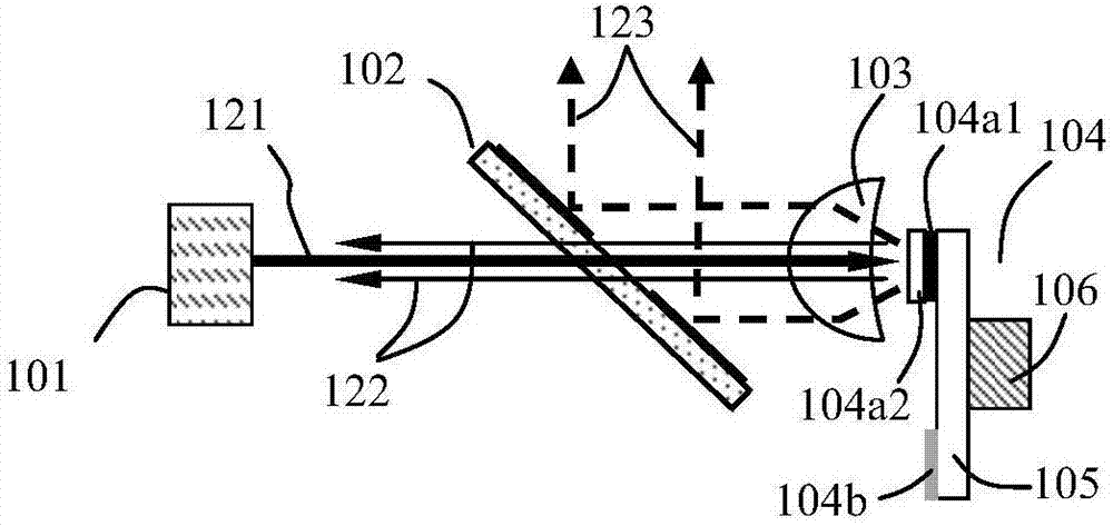
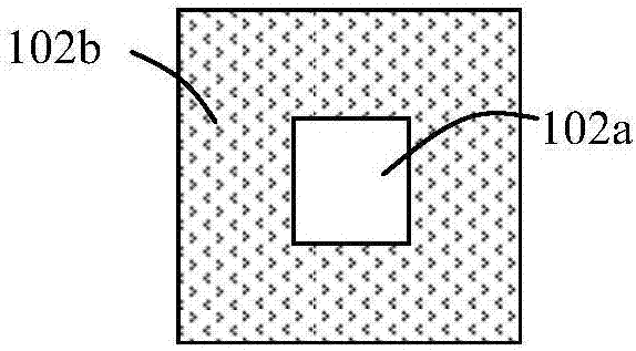
[0018] The present invention proposes a light emitting device, the structural schematic diagram of the first embodiment is as follows figure 1 shown. The light emitting device includes a laser light source 101 for emitting primary laser light 121 , and also includes a beam splitting device 102 and a light concentrating device 103 located at the rear end of the light path of the beam splitting device. Among them, such as image 3 As shown, the spectroscopic device 102 includes a lead-in region 102a and a lead-out region 102b, and the original laser light 121 emitted by the laser light source 101 is incident on the lead-in region 102a of the spectroscopic device.

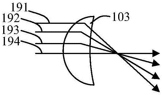
[0019] The light emitted from different areas on the spectroscopic device 102 will be in different angular ranges after being concentrated by the light-condensing device 103, that is, the angular distribution range of the light emitted from the introduction area 102a after being concentrated by the light-condensing d...


PUM


Abstract

A light-emitting device and a projection display device are proposed, including a laser light source for emitting original laser light, a light-splitting device and a light-gathering device located at the rear end of the light path of the light-splitting device, wherein the light-splitting device includes a lead-in area and a lead-out area; wavelength conversion is also included The wavelength conversion device includes a wavelength conversion section and a reflection scattering section. The wavelength conversion section includes a reflection layer and a wavelength conversion layer covering the surface of the reflection layer, and also includes a functional filter and a driving device covering the surface of the wavelength conversion layer. The lead-in area of ​​the light splitting device reflects the laser light, the lead-out area transmits the laser light, and both the lead-in area and the lead-out area transmit the received light. Using the cooperation of the two areas of the spectroscopic device and the functional filter, the first scattered laser light emitted from the wavelength conversion section is successfully suppressed and cannot be emitted, and at the same time, most of the second scattered laser light emitted from the reflective scattering section can be suppressed. shoot.

Description

technical field [0001] The invention relates to the field of light sources, in particular to a light emitting device and a projection display device using the light emitting device. Background technique [0002] At present, the laser excites the rotating phosphor turntable to generate time-sharing fluorescence, and this method has been widely used in the projection display industry. However, the current solutions either have complex structures or impure colors of emitted light, which have certain defects. Therefore, there is a great need for a solution that is efficient, compact, and has a good color of the emitted light. Contents of the invention [0003] The present invention proposes a light-emitting device, which includes a laser light source for emitting primary laser light, a spectroscopic device and a light concentrating device located at the rear end of the optical path of the spectroscopic device, wherein the spectroscopic device includes a lead-in area and a lea...

Claims


Application Information

Patent Timeline
Patent Type & Authority Patents(China)
IPC IPC(8): G03B21/20G02B26/00G02B27/10
Inventor 杨毅
Owner 杨毅
Why Eureka
Try Eureka