Strike pad

A technology of percussion pads and percussion surfaces, applied to percussion instruments, musical instruments, electro-acoustic instruments, etc., which can solve the problem of insufficient displacement of the pad 101

Inactive Publication Date: 2015-12-23
YAMAHA CORP
View PDF8 Cites 2 Cited by
  • Summary
  • Abstract
  • Description
  • Claims
  • Application Information

AI Technical Summary

Problems solved by technology

However, the elastic deformation of the thin-walled portion 102 at the time of impact is mainly simple elongation like

Method used


Image

  • Strike pad
  • Strike pad
  • Strike pad

Examples


Embodiment Construction

[0019] Hereinafter, a percussion pad according to an embodiment of the present invention will be described with reference to the drawings.

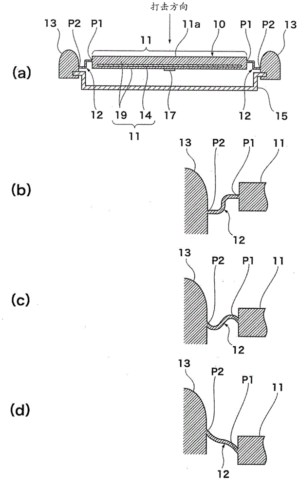
[0020] figure 1 (a) is a schematic sectional view of the striking pad according to one embodiment of the present invention, showing a non-strike state. It is assumed that the percussion pad of the present invention is suitable for electronic percussion instruments, but it is not limited thereto. For example, it can also be configured as a special pad for practice.

[0021] The pad 10 has a pad portion 11 , a connection portion 12 , a hoop portion 13 , and a case 15 . The casing 15 is placed on the ground or supported on the ground via a not-shown stand. The pad portion 11 has a soft portion 19 and a hard member 14 . A hard member 14 such as an iron plate is enclosed in the soft part 19 as a core material. The soft part 19 is softer than the hard member 14, and is formed integrally with the connection part 12 and the hoop part 13 usin...


PUM


Abstract

The invention provides a strike pad. In a strike pad (10), a soft portion (19) such as rubber materials with elasticity, internally covers a hard part (14) such as an iron plate, served as a core material, to form a pad portion (11); the pad portion (11) is connected to a drum rim portion (13) via a connection portion (12); in the state of non-strike, a first connection position (P1) of the connection portion(12) relative to the pad portion (10) in the strike direction is more near the opposite side of the strike direction than a second connection position (P2) of the connection portion (12) relative to the drum rim (13).

Description

[0001] technology area [0002] The present invention relates to a striking pad which is suitable for percussion instruments and the like and has a pad portion having a striking surface to be struck. Background technique [0003] A percussion pad suitable for a percussion instrument or the like is supported on a supporting portion such as a drum frame or a resonance box, and the striking surface of the pad portion is struck by the striking member. As a prior art, as shown in the following patent document 1, the structure in which a pad part is supported by a support part via a thin part is known. [0004] Figure 5 (a) and Figure 5 (b) is a sectional view showing a modeled support structure of a conventional pad, and shows a non-shock state and a hit state, respectively. [0005] The pad 100 is formed by connecting a pad portion 101 to a hoop portion 103 via a thin portion 102, and the pad portion 101 includes a hard member 104 such as an iron plate as a core material in a s...

Claims


Application Information

Patent Timeline
IPC IPC(8): G10D13/00G10H3/14G10H1/00
Inventor 西田贤一保田善彦伊东宽明
Owner YAMAHA CORP
Why Eureka
Try Eureka