
A laser pulse switch device and its control method

A laser pulse and switching device technology, applied in lasers, laser components, phonon exciters, etc., can solve problems such as damage to laser stability, high price, and difficult production

Active Publication Date: 2018-02-13
PEKING UNIV
View PDF6 Cites 0 Cited by
  • Summary
  • Abstract
  • Description
  • Claims
  • Application Information

AI Technical Summary

Problems solved by technology

Considering the damage energy of the laser pulse, the higher the energy of the laser pulse, the larger the spot size. Therefore, if a switch is added after the KHz laser is amplified, a single shot can be achieved, and the aperture of the switch is also small, but there is no seed for the subsequent multi-pass amplification The light will extract the pump energy, and the thermal effect of the laser will be different from that of the laser at a certain repetition rate. At this time, a single-shot operation of the laser will damage the stability of the laser.
If a switch is added after the amplifier system, damage to the laser stability can be avoided, but the spot size is too large at this time. For hundreds of TW lasers, the size is tens of mm. It is used in a position with high energy, so the return light brought at the moment of shutdown is a huge hazard to the 100 TW laser

Method used


Image

  • A laser pulse switch device and its control method
  • A laser pulse switch device and its control method
  • A laser pulse switch device and its control method

Examples


Embodiment Construction

[0032] The present invention will be further described through the embodiments below in conjunction with the accompanying drawings.

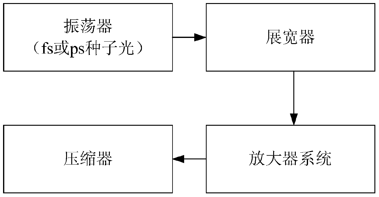
[0033]Such as figure 1 As shown, the chirped laser pulse amplification system includes: oscillator, stretcher, amplifier system and compressor.

[0034] Such as figure 2 As shown, the amplifier system includes a KHz amplifier, a Pockels cell and a multi-pass amplifier group, and two pump sources provide pump light for the KHz amplifier and the multi-pass amplifier group respectively.

[0035] The stretched long laser pulse is first amplified by a KHz amplifier, and the KHz amplifier is powered by a KHz pump source. Because the pumping source of the KHz amplifier is an all-solid-state laser pumped by LD, its stability is high, so the KHz amplifier has higher stability, and the stability of the system can be improved by using the KHz amplifier as the front-end amplification. The laser pulse amplified by the KHz amplifier will be sent to the su...


PUM


Abstract

The invention discloses a laser pulse switch apparatus and a control method therefor. According to the laser pulse switch apparatus and the control method therefor, a first switch and a second switch are arranged behind a pockels cell and a multipass amplifier set respectively to form a two-switch single-shot system, a single pulse trigger signal is generated by inputting a laser synchronous signal into a delayer, and the first switch is controlled to be on once only, so that single-shot emission of laser pulses is realized; the first switch realizes that one laser pulse is quickly selected for passing, and the second switch takes effect of blocking light; the aperture and speed of the switch are realized by two switches respectively, so that the requirements on the aperture of the first quick switch and the speed of the second large-aperture switch are reduced; any change is not performed on a pump light path, so that the heat effect, the beam quality and the like of pump laser pulses are not changed and it is ensured that the quality of the whole laser device is not changed; and when a shooting range does not need the laser pulses subsequently, it can be ensured that the energy of the high-energy laser pulses in the multipass amplifier set is not accumulated for causing the problems of the heat effect and the like.

Description

technical field [0001] The invention relates to high-energy particle acceleration technology, in particular to a laser pulse switch device and a control method thereof. Background technique [0002] After the chirped laser pulse amplification system (CPA) was proposed, the peak power of the laser developed rapidly, and the peak power of the laser pulse could reach several PW (10 15 W), the intensity of the laser pulse can reach 10 22 W / cm2. Such high-field laser pulses are widely used in laser-target interactions. Especially when the laser pulse interacts with the shooting range, since the laser will destroy the target after the laser pulse interacts with the shooting range, the target needs to be replaced when the next laser pulse interacts with the shooting range. Laser pulses can be artificially controlled to achieve single-shot lasing. However, the actual laser has a certain repetition rate. At present, the repetition frequency of the hundred terawatt (TW) and petawa...

Claims


Application Information

Patent Timeline
Patent Type & Authority Patents(China)
IPC IPC(8): H01S3/10H01S3/0955
Inventor 赵研英廖庆颜学庆马文君卢海洋林晨耿易星李荣凤
Owner PEKING UNIV
Learn More