Simple stereoscope for allowing side-by-side image to be seen as three-dimensional image

A stereoscopic mirror and image playback technology, applied in the field of stereoscopic mirrors, can solve problems such as unclear distance between eyes, and achieve the effects of convenient viewing, reducing eye fatigue, and reducing manufacturing costs

Inactive Publication Date: 2015-12-23
GOGGLE TECH
View PDF7 Cites 1 Cited by
  • Summary
  • Abstract
  • Description
  • Claims
  • Application Information

AI Technical Summary

Problems solved by technology

When it is a structure in which the distance between the two lenses 2 cannot be adjusted, the disadvantage is that it is necessary to manufacture a variety of products with different lens distances
In addition, users generally do not know the distance between their eyes, so it is inconvenient that they need to try on multiple products in person to choose a product that suits their eye distance.

Method used


Image

  • Simple stereoscope for allowing side-by-side image to be seen as three-dimensional image
  • Simple stereoscope for allowing side-by-side image to be seen as three-dimensional image
  • Simple stereoscope for allowing side-by-side image to be seen as three-dimensional image

Examples


no. 1 example

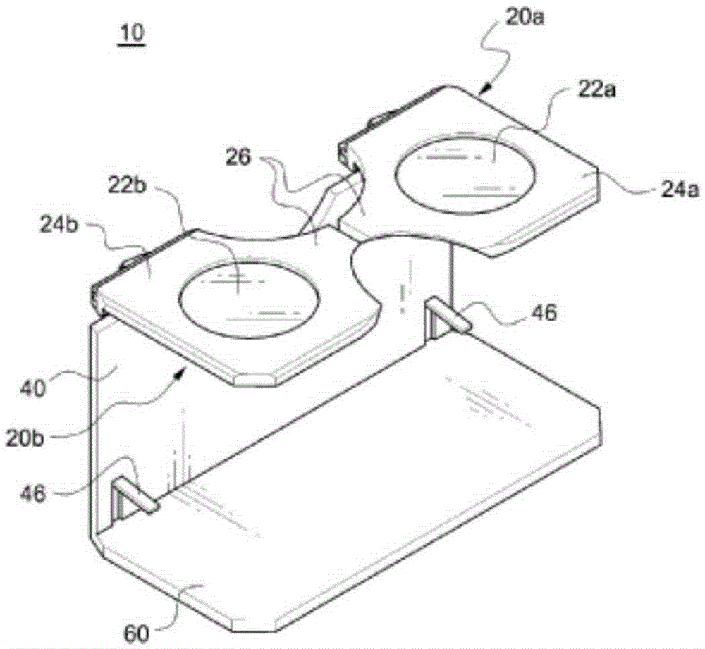
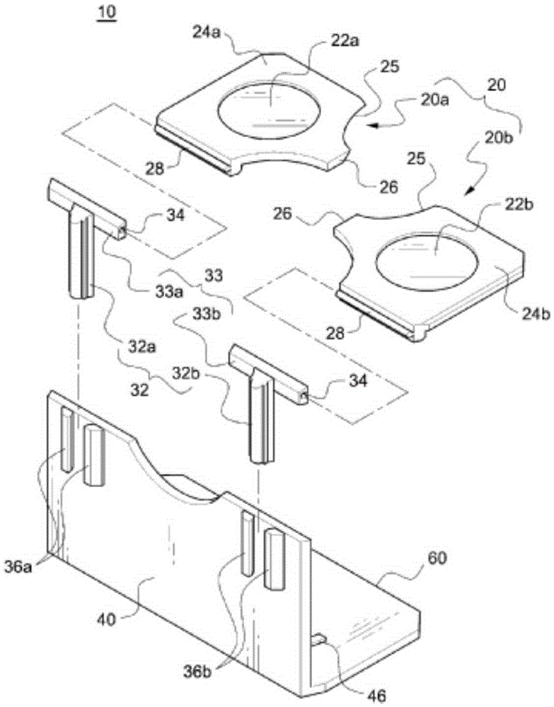
[0029] first, Figure 2 to Figure 4 A stereoscope 10 according to a first embodiment of the invention is shown. The stereoscopic mirror 10 includes a lens height adjustment portion 30 . The lens height adjusting part 30 is provided with two guide parts 36a, 36b formed in the same structure on the left and right sides of the back surface of the plate-shaped vertical support member 40, respectively. Each guide part 36a or 36b is configured such that two guide rods are spaced apart by a predetermined distance in the horizontal direction and fixed to the rear surface of the vertical support member 40 in a state extending parallel to the vertical direction. Each guide portion 36a, 36b provides a linear guide groove along the vertical direction.

[0030] First and second height adjustment rods 32a, 32b capable of sliding in the vertical direction are respectively inserted into the guide grooves of the two guide portions 36a, 36b. The height adjustment rods 32a, 32b are used to ad...

no. 3 example

[0044] Figure 8 to Figure 12 It is a perspective view of the assembly state of the structure of the stereoscopic mirror 200 according to the third embodiment of the present invention, a state view of the folded temple parts 230a, 230b, a use state view of installing the video player 70 such as a smart phone, and disassembled two lenses 22a , 22b, and the state when the distance between the two lenses 22a, 22b is adjusted to the maximum and minimum.

[0045] Compared with the first two embodiments, the stereoscopic mirror 200 according to the third embodiment is different in that its overall shape is designed in the shape of glasses, and the left and right temple parts 230a, 230b are foldable, and are configured as though the two lenses 22a, 22b The distance between them can be adjusted, but the height of the two lenses 22a, 22b from the screen of the video player (for example: smart phone) 70 cannot be adjusted.

[0046] More specifically, the stereoscopic mirror 200 include...


PUM


Abstract

A simple stereoscope for viewing a side-by-side image is disclosed. The stereoscope (10, 100) comprises lens height-adjusting parts (30) for holding a first lens part and a second lens part such that the vertical heights of a first lens and a second lens can be adjusted within the range from a first height to a second height while the first lens and the second lens are placed side to side so as to be parallel with a horizontal direction. Furthermore, the stereoscope can further comprise lens interval-adjusting parts (50, 150) capable of adjusting horizontal intervals between the center of the first lens and the center of the second lens within a predetermined range. The stereoscope can also be formed by comprising an eyeglass frame and eyeglass temples and allowing a horizontal diameter of a lens mounting part of the eyeglass frame to be larger than that of the lenses so as to adjust the horizontal intervals of the two lenses.

Description

technical field [0001] The present invention relates to a stereoscope (stereoscope), which is used as a tool for viewing stereoscopic images, and relates to a simple stereoscope in more detail, which can view side-by-side (stereo) images as stereoscopic images. image to watch. Background technique [0002] When a person observes things with two eyes, the image of the same object viewed at slightly different angles due to the distance between the left eye and the right eye is presented on the retina through the two eyeballs and then transmitted to the brain. After receiving the two images, the human brain synthesizes them to recognize the sense of distance in the three-dimensional space. Recently, with the widespread acceptance of three-dimensional stereoscopic images, the production and consumption of stereoscopic images are increasing. As one of the existing technologies capable of watching stereoscopic images, its principle is the same as that of people feeling the stere...

Claims


Application Information

Patent Timeline
Patent Type & Authority Applications(China)
IPC IPC(8): G02B27/22
CPCG02B27/027G02B27/04G02B30/37G02F1/133512G02B30/25G02B30/34
Inventor 崔在赫
Owner GOGGLE TECH
Why Eureka
Try Eureka