Part placement rack

A technology for placing racks and parts, applied in the direction of workbench, manufacturing tools, etc., can solve the problems of low oil removal efficiency, troublesome work, and inability to remove cooling oil, etc., and achieve the effect of ingenious structural design and high efficiency

Inactive Publication Date: 2015-12-30
CHONGQING RUIJIA MACHINERY CO LTD
View PDF7 Cites 3 Cited by
  • Summary
  • Abstract
  • Description
  • Claims
  • Application Information

AI Technical Summary

Problems solved by technology

However, the structure design of the existing rack is unreasonable, resulting in low oil removal efficiency, and most of the cooling oil cannot be removed after the parts are placed for a long time, which brings troubles to the follow-up work

Method used


Image

  • Part placement rack
  • Part placement rack
  • Part placement rack

Examples


Embodiment 1

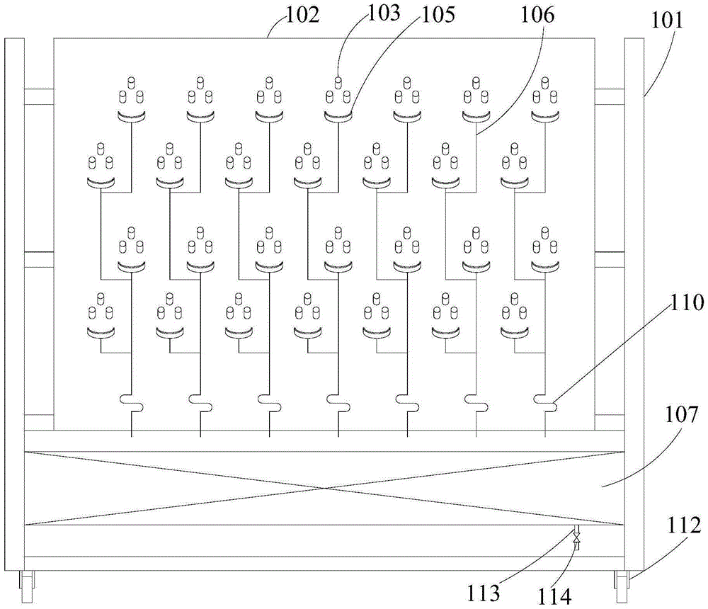
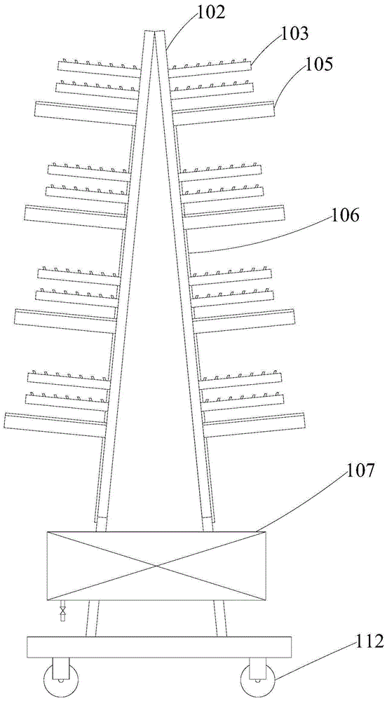
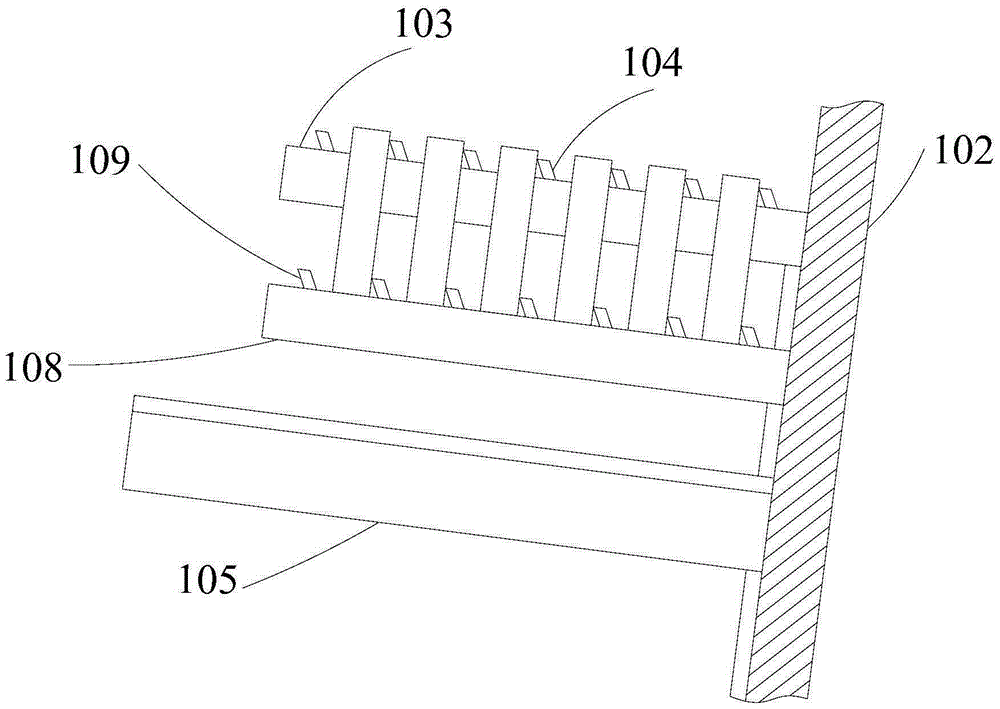
[0059] A parts placement rack, comprising a frame body 101, the frame body 101 includes a placement area and an oil collection area from top to bottom; the placement area includes two sets of suspension mechanisms arranged symmetrically along the vertical plane, and each set of suspension mechanisms includes a Hanging plate 102, each hanging plate 102 is provided with 28 groups of suspension components, the suspension components are divided into four rows, each row has 7 groups; each group of suspension components includes hanging rods 103 arranged obliquely, and the upper part of the hanging rods 103 is along its Seven stoppers 104 are evenly spaced in the length direction, and each set of suspension components also includes an arc-shaped oil collecting plate 105 obliquely arranged under the hanging rod 103, and the bottom end of the oil collecting plate 105 is connected with an oil pipe extending downward 106 ; the oil collecting area includes an oil collecting groove 107 arr...

Embodiment 2

[0061] A parts placement rack, comprising a frame body 101, the frame body 101 includes a placement area and an oil collection area from top to bottom; the placement area includes two sets of suspension mechanisms arranged symmetrically along the vertical plane, and each set of suspension mechanisms includes a Hanging board 102, two hanging boards 102 are all obliquely arranged, and its top is connected, and the bottom is far away from each other, and each hanging board 102 is provided with 28 groups of suspension assemblies, and suspension assembly is divided into four rows, and each row has 7 groups; The set of suspension components includes a hanging rod 103 arranged obliquely. The upper part of the hanging rod 103 is evenly spaced with seven stoppers 104 along its length direction. plate 105, the bottom of this oil collecting plate 105 is connected with oil pipe 106 extending downwards, each hanging rod 103 and each oil collecting plate 105 are all perpendicular to hanging ...

Embodiment 3

[0064] A parts placement rack, comprising a frame body 101, the frame body 101 includes a placement area and an oil collection area from top to bottom; the placement area includes two sets of suspension mechanisms arranged symmetrically along the vertical plane, and each set of suspension mechanisms includes a Hanging board 102, two hanging boards 102 are all obliquely arranged, and its top is connected, and the bottom is far away from each other, and each hanging board 102 is provided with 28 groups of suspension assemblies, and suspension assembly is divided into four rows, and each row has 7 groups; The set of suspension components includes a hanging rod 103 arranged obliquely. The upper part of the hanging rod 103 is evenly spaced with seven stoppers 104 along its length direction. plate 105, the bottom of this oil collecting plate 105 is connected with oil pipe 106 extending downwards, each hanging rod 103 and each oil collecting plate 105 are all perpendicular to hanging ...


PUM


Abstract

The invention provides a part placement rack and belongs to the field of auxiliary equipment for the machining industry. The part placement rack comprises a rack body, wherein the rack body comprises a placement area and an oil collecting area from top to bottom; the placement area comprises two groups of suspension mechanisms symmetrically arranged along a vertical surface, each suspension mechanism comprises a suspending plate, multiple groups of suspension assemblies are arranged on the suspending plate, each group of suspension assembly comprises an inclined suspending rod, multiple blocking pieces are arranged at the upper part of the suspending rod in the length direction at equal intervals, each group of suspension assembly further comprises an arc oil collecting plate obliquely arranged below the suspending plate, and an oil pipe extending downwards is connected with the bottom end of the oil collecting plate; the oil collecting area comprises an oil collecting tank arranged below the suspending plates. When the part placement rack is in use, multiple parts are suspended on the part placement rack, and the purpose of oil removal can be achieved; each part cannot be contacted with other parts, and the oil removal efficiency is higher; further, the structural design of the part placement rack is ingenious, and multiple parts can be suspended.

Description

technical field [0001] The invention relates to the field of auxiliary equipment in the mechanical processing industry, in particular to a parts placing rack. Background technique [0002] In the machining industry, ring-shaped parts are very common, such as the inner and outer rings of bearings, the ring gear of gears, etc. During the processing of such parts, cooling oil is used in multiple processes to prevent parts and tools from overheating. After the parts are processed, they need to be packaged or transported to the next production line for assembly. At this time, the parts need to be degreased to remove most of the cooling oil attached to the parts to facilitate subsequent work. [0003] When doing this work, the parts are generally hung on the rack, so that the cooling oil on the parts will flow down slowly under the action of gravity. This method is relatively simple and low cost, so it is widely used. However, the unreasonable structure design of the existing ra...

Claims


Application Information

Patent Timeline
Patent Type & Authority Applications(China)
IPC IPC(8): B25H1/06
CPCB25H1/06
Inventor 刘自力
Owner CHONGQING RUIJIA MACHINERY CO LTD
Why Eureka
Try Eureka