Draught fan absorber and draught fan

A technology of shock absorbers and fans, which is applied in the direction of machines/engines, mechanical equipment, liquid fuel engines, etc., can solve the problems of high-power or medium-power fans with large resonance vibration, low fan performance, and high operating noise, so as to eliminate resonance. phenomenon, improve fan performance, reduce the effect of operating noise

Active Publication Date: 2015-12-30
GREE ELECTRIC APPLIANCES INC
View PDF4 Cites 5 Cited by
  • Summary
  • Abstract
  • Description
  • Claims
  • Application Information

AI Technical Summary

Problems solved by technology

[0002] The vibration of high-power and medium-power centrifugal fans or cross-flow fans is relatively large. One of the important reasons is that the motor itself vibrates greatly, and the motor transmits vibration to other fan parts, such as impellers, through the motor shaft, casing and its bracket. , resulting in a large vibration of the impeller, the impeller is easy to resonate with the motor and the volute, the destructive force of the resonance is relatively large, and the operating noise is relatively large, which seriously affects the product performance of the fan
[0003] At present, in order to solve the problem of fan vibration, rubber gaskets are added between the motor and the impeller to reduce vibration. However, the vibration reduction effect of rubber gaskets is more obvious for small-power fans, but it is not good for high-power or medium-power fans. Obviously, the resonance vibration of high-power or medium-power fans is still relatively large, and the operating noise is still high, resulting in low fan performance

Method used


Image

  • Draught fan absorber and draught fan
  • Draught fan absorber and draught fan
  • Draught fan absorber and draught fan

Examples


Embodiment Construction

[0047] The technical solutions in the embodiments of the present invention will be clearly and completely described below with reference to the accompanying drawings in the embodiments of the present invention. Obviously, the described embodiments are only a part of the embodiments of the present invention, but not all of the embodiments. Based on the embodiments of the present invention, all other embodiments obtained by those of ordinary skill in the art without creative efforts shall fall within the protection scope of the present invention.

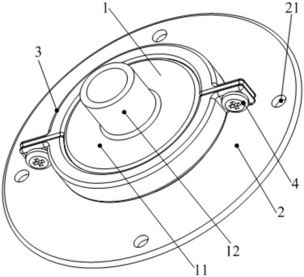
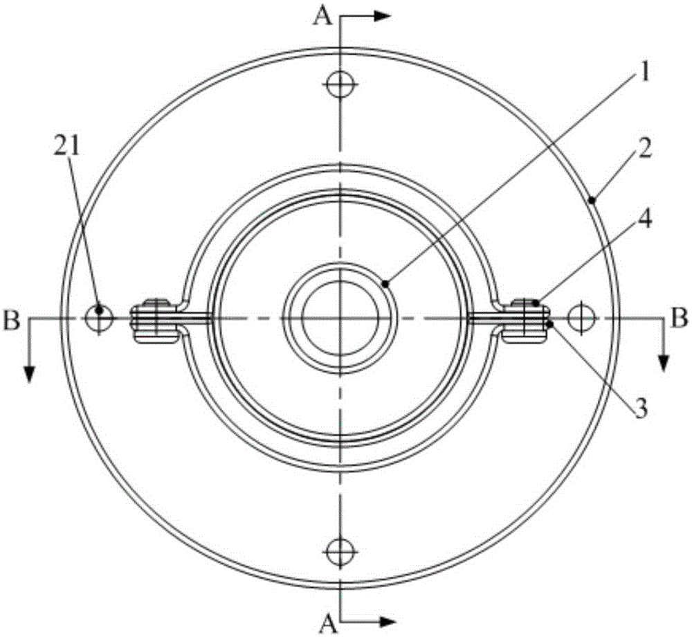
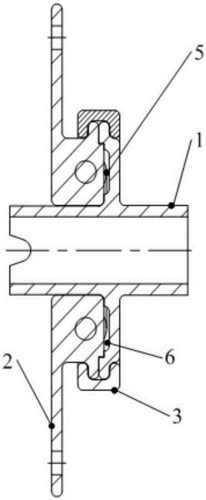
[0048] The fan shock absorber provided by the embodiment of the present invention includes: a driving wheel 1, a driven wheel 2, a first transmission member 7, a second transmission member 8 and a vibration damping member 5; wherein, the driving wheel 1 is used for driving with the motor of the fan Connection; the driven wheel 2 is used for driving connection with the impeller of the fan, the driving wheel 1 and the driven wheel 2 are ...


PUM


Abstract

The invention discloses a draught fan absorber and a draught fan. The draught fan absorber comprises a drive wheel used for transmission connection with a motor of the draught fan, a driven wheel used for transmission connection with an impeller of the draught fan, a first transmission part fixed to the drive wheel, a second transmission part fixed to the driven wheel, and a vibration reduction part connected with the first transmission part and the second transmission part along the circumference direction of the drive wheel, wherein the drive wheel and the driven wheel are relatively fixed along an axial direction, a placing cavity is formed between the driven wheel and the drive wheel, the first transmission part, the vibration reduction part and the second transmission part are all located in the placing cavity, and the drive wheel drives the driven wheel to rotate by the first transmission part, the vibration reduction part and the second transmission part. According to the draught fan absorber disclosed by the invention, vibration is reduced by the vibration reduction part in a torque transmitting process, and the vibration of the draught fan is reduced, thus reducing the running noise of the draught fan and improving the performance of the draught fan.

Description

technical field [0001] The invention relates to the technical field of fan vibration damping, and more particularly, to a fan shock absorber and a fan. Background technique [0002] High-power and medium-power centrifugal fans or cross-flow fans have large vibrations. One of the important reasons is that the motor itself vibrates greatly. The motor transmits the vibration to other fan parts, such as the impeller, through the motor shaft, casing and its bracket. , resulting in larger vibration of the impeller, the impeller is more likely to resonate with the motor and the volute, the destructive force of the resonance is larger, and the operating noise is larger, which seriously affects the product performance of the fan. [0003] At present, in order to solve the vibration problem of the fan, the vibration is reduced by adding a rubber gasket between the motor and the impeller. However, the vibration reduction effect of the rubber gasket is obvious for low-power fans, but no...

Claims


Application Information

Patent Timeline
Patent Type & Authority Applications(China)
IPC IPC(8): F04D29/66F04D25/06
Inventor 陈运波杨勇
Owner GREE ELECTRIC APPLIANCES INC
Why Eureka
Try Eureka