


Quick Research
Generate reliable direction feasibility study reports for your R&D in just a few steps.

Technical Q&A
Discover and master advanced knowledge NOW. Basics, ideas, possibilities, all at once.

Find Solutions
As an expert in R&D theories, this can generate solutions to your technical problems instantly.

Evaluate Feasibility
Analyze your overall solution with one click, know your potential R&D risks in advance.

Monitor Landscape
Get weekly tech updates, stay abreast of the latest tech innovations and key insights.
Lubricated bearing for petroleum drilling
A technology for lubricating bearings and oil drilling, applied in the direction of bearing components, shafts and bearings, rigid supports of bearing components, etc., can solve problems such as large gaps and lubricating oil cannot flow into the other end
- Summary
- Abstract
- Description
- Claims
- Application Information
AI Technical Summary
Problems solved by technology
Method used
Image

Examples
Embodiment Construction
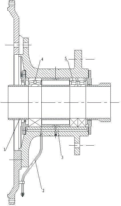
[0011] Such as figure 1 As shown, there is a three-way oil channel 5 in the equipment 1, and the lubricating oil enters the equipment from the lubricating oil inlet pipeline 4, and then flows into the rolling bearings, bearing I2, and bearing II3 at both ends of the lubricating oil along the oil hole channel in the equipment 1. This design draws lessons from the idea and method of forced lubricating bearing bush or sliding bearing, and improves it, forming a new method of forcing rolling bearings at both ends of the equipment at the same time.
[0012] A lubricating bearing for oil drilling, comprising equipment 1, bearing I2 and bearing II3 installed on the equipment 1, oil inlet pipeline 4 and oil passage 5 inside the equipment are arranged on the equipment 1. The oil passage 5 can lead the oil passage 5 to the inside of the equipment 1 that needs to be filled with grease through an additional pipeline. Oil holes are arranged on the outer bearing caps of the bearing I2 and ...
PUM
 Abstract
Description
Claims
Application Information
 - R&D Engineer
- R&D Manager
- IP Professional
- Industry Leading Data Capabilities
- Powerful AI technology
- Patent DNA Extraction
Browse by: Latest US Patents, China's latest patents, Technical Efficacy Thesaurus, Application Domain, Technology Topic, Popular Technical Reports.
© 2024 PatSnap. All rights reserved.Legal|Privacy policy|Modern Slavery Act Transparency Statement|Sitemap|About US| Contact US: help@patsnap.com