Liquid level controller

A technology of liquid level controller and float switch, which is applied in the direction of liquid level control, non-electric variable control, control/regulation system, etc. It can solve problems such as inability to install, long binding wire length, and limitations in pump control, and achieve reduction The effect of reducing volume, avoiding breakage, and reducing production costs

Inactive Publication Date: 2015-12-30
司捷易兰姆布斯控制科技(苏州)有限公司
View PDF14 Cites 3 Cited by
  • Summary
  • Abstract
  • Description
  • Claims
  • Application Information

AI Technical Summary

Problems solved by technology

Due to the limited space, the traditional float switch has a long tie wire length, so it cannot be placed in these applications and installed properly, resulting in limitations on the control of the pump

Method used


Image

  • Liquid level controller
  • Liquid level controller
  • Liquid level controller

Examples


Embodiment Construction

[0037] The technical solutions of the present invention will be further described in detail below in conjunction with the embodiments and accompanying drawings, but the protection scope of the present invention is not limited to the embodiments.

[0038] A. Overview.

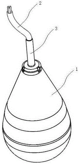
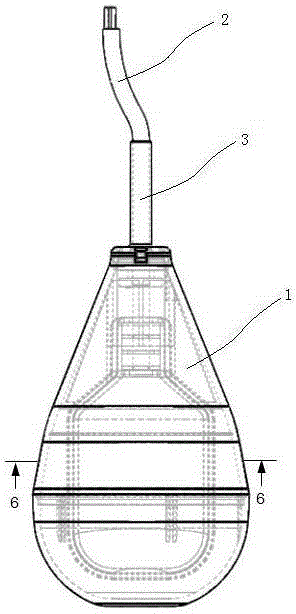
[0039] Turning now descriptively to the drawings, wherein like reference numerals represent like elements throughout the several views, Figures 1 to 11 A liquid level controller is described, including an outer casing 1, a float switch 7 built in the outer casing 1, and a sealing block and a counterweight 13 arranged in the outer casing 1 and surrounding the float switch 7.

[0040] B. Outer shell.

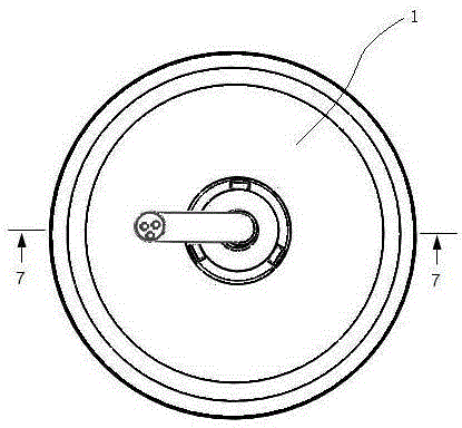
[0041] as attached Figures 1 to 4 As shown, the outer casing 1 is located on the outermost layer, and there is a cavity inside it for accommodating other components to obtain buoyancy in liquid, and prevent liquid or gas from entering the internal cavity to corrode the electrical components through sealing.

[...


PUM


Abstract

The invention discloses a liquid level controller which comprises a floating ball switch, and is characterized in that a shell sleeves the floating ball switch in such a manner that an interlayer is formed between the shell and the outer wall of the floating ball switch; a balancing weight is fixed in the upper half part of the interlayer. The liquid level controller has the benefits that a sealing block made of a foaming agent is arranged in the shell, so as to avoid the potential hazard that the floating ball sinks when the plastic shell breaks and water enters the broken shell; the balancing weight can provide a certain weight to make the liquid level controller more stable in a liquid, so as to reduce the length of a binding thread, and ensure that the liquid level controller is particularly suitable for circumstances such as a shaft and a relative small tank body; the shell is sealed, so as to provide sufficient buoyancy force to ensure normal use, and prevent the liquid from entering the shell to erode and damage related electric elements in the shell.

Description

technical field [0001] The present invention generally relates to a liquid level controller, and more particularly relates to a liquid level controller used in a narrow environment. Background technique [0002] Any discussion of related art throughout this specification should not be taken as an admission that such related art is well known or forms a part of the common general knowledge in the field. [0003] Float switches are used to determine the liquid level in tanks or other water holding structures. Float switches are electrically connected to pumps (such as sump pumps, condensate pumps), indicators, alarms, control panels or other equipment. Conventional float switches are comprised of a single-walled housing defining a sealed cavity, both of which protect the switch within the sealed cavity and provide buoyancy to float in liquids (eg, water, waste water). The switch within the housing is typically a two-stage switch comprising a ball disposed within a channel, a...

Claims


Application Information

Patent Timeline
Patent Type & Authority Applications(China)
IPC IPC(8): G05D9/12
Inventor 周剑波
Owner 司捷易兰姆布斯控制科技(苏州)有限公司
Why Eureka
Try Eureka