Self-service charging pile for electrical vehicle
A technology for electric vehicles and charging piles, applied in electric vehicles, battery circuit devices, current collectors, etc., can solve the problems of inability to accurately determine the amount of electricity required for full battery, the battery cannot be fully charged or overcharged, etc., to achieve payment methods Variety, easy to use, high sensitivity
- Summary
- Abstract
- Description
- Claims
- Application Information
AI Technical Summary
Problems solved by technology
Method used
Image
Examples
Embodiment 1
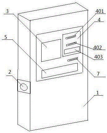
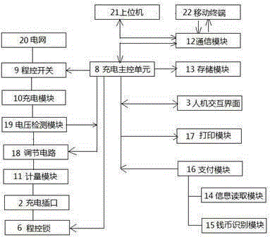
[0029] In order to overcome the problem that the electric vehicle charging pile in the prior art adopts the prepayment method, people cannot accurately judge the required amount of electricity for the battery to be fully charged, resulting in the battery being unable to be fully charged or overcharged, and the payment method cannot meet the needs of users. This embodiment provides a kind of figure 1 and figure 2 A self-service electric vehicle charging pile shown includes a charging pile body 1 and a control system thereof. Wherein, a charging socket 2 is provided on one side of the charging pile body 1 , and a program-controlled lock 6 is provided in the charging socket 2 . A man-machine interface 3 , a payment panel 4 and a print outlet 7 are arranged on the upper front of the charging pile body 1 . In the middle of the front of the charging pile body 1, there is an operation instruction signboard 5 pasted on it.
[0030] It should be noted that, in order to improve the ...
Embodiment 2
[0036] In this embodiment, on the basis of Embodiment 1, as a preferred implementation manner, the charging main control unit 8 adopts a CPLD controller.
[0037] As a preferred embodiment, the line between the charging module 10 and the metering module 11 is further provided with a voltage detection module 19 and an adjustment circuit 18 for adjusting the output voltage in sequence.
[0038] In this embodiment, the voltage detection module 19 monitors the load of the power grid 20 in real time, and feeds back information to the charging main control unit 8. The charging main control unit 8 receives the information transmitted by the voltage detection module 19 for analysis and processing, and then sends to the adjustment circuit 18 whether to adjust the charging. load instructions.
Embodiment 3
[0040] This embodiment combines Embodiments 1 and 2. As a preferred implementation, the payment module 16 includes a coin identification module 15 and an information reading module 14 . As a preference, the coin recognition module 15 is a banknote validator, and the information reading module 14 is an IC card reader.
[0041] In this embodiment, the coin identification module 15 receives and identifies banknotes and transmits the denomination of the banknotes to the charging main control unit 8 , and the information reading module 14 reads the information on the IC card and transmits the information to the charging main control unit 8 .
[0042] As a preferred embodiment, the communication module 12 includes a wireless communication interface and a WIFY unit, and the user can use a smart phone to communicate with the charging main control unit 8, download electronic bills, and make online payment.
[0043] In this embodiment, the setting of the payment module 16 can select cas...
PUM
 Abstract
Description
Claims
Application Information
 - R&D
- Intellectual Property
- Life Sciences
- Materials
- Tech Scout
- Unparalleled Data Quality
- Higher Quality Content
- 60% Fewer Hallucinations
Browse by: Latest US Patents, China's latest patents, Technical Efficacy Thesaurus, Application Domain, Technology Topic, Popular Technical Reports.
© 2025 PatSnap. All rights reserved.Legal|Privacy policy|Modern Slavery Act Transparency Statement|Sitemap|About US| Contact US: help@patsnap.com


