Video monitoring system for video-wall configuration

A technology of video monitoring system and video wall, which is applied in the direction of closed-circuit television system, etc., and can solve the problems of losing video wall, high cost, limited number of equipment interfaces, etc.

Active Publication Date: 2015-12-30
武汉微创光电股份有限公司
View PDF6 Cites 20 Cited by
  • Summary
  • Abstract
  • Description
  • Claims
  • Application Information

AI Technical Summary

Problems solved by technology

[0007] Disadvantages: When using 2 or more DVRs or NVRs, it is impossible to realize arbitrary control and combined switching of images, and can only display video channels that are limited to the management of the DVR or NVR host itself. The flexibility is very low, and the real existence of the TV wall is lost. the meaning of
[0011] Disadvantages: The video switching display is not flexible, it is necessary to set the decoding video source on the decoder, the operation is cumbersome, and the user interface is not friendly
[0015] Disadvantages: high cost, using the X86 architecture to run the ordinary WINDOWS operating system, there are also great hidden dangers in its security and stability
[0019] Disadvantages: limited by the number of interfaces of the device itself, the flexibility is not enough, a matrix device needs to be added, and the cost is high
[0020] Some of the above solutions cannot flexibly switch the video source displayed on the monitor, some are cumbersome to operate, and the user interface is not friendly, and some limit the expansion of the system due to the limited hardware interface, all of which limit the distributed monitoring system. Development does not conform to its openness and flexibility, so we propose to use software to configure the design of the TV wall solution, add the TV wall configuration function to the system, complete the layout configuration of the monitor, and complete the association between the monitor and the decoder Configuration, complete the dynamic association configuration of monitors and media sources (groups) to achieve flexible image viewing, that is, any display can view any front-end camera without being restricted by physical or logical network structure

Method used


Image

  • Video monitoring system for video-wall configuration
  • Video monitoring system for video-wall configuration
  • Video monitoring system for video-wall configuration

Examples


Embodiment Construction

[0034] The following will clearly and completely describe the technical solutions in the embodiments of the present invention with reference to the accompanying drawings in the embodiments of the present invention. Obviously, the described embodiments are only some, not all, embodiments of the present invention. Based on the embodiments of the present invention, all other embodiments obtained by persons of ordinary skill in the art without making creative efforts belong to the protection scope of the present invention.

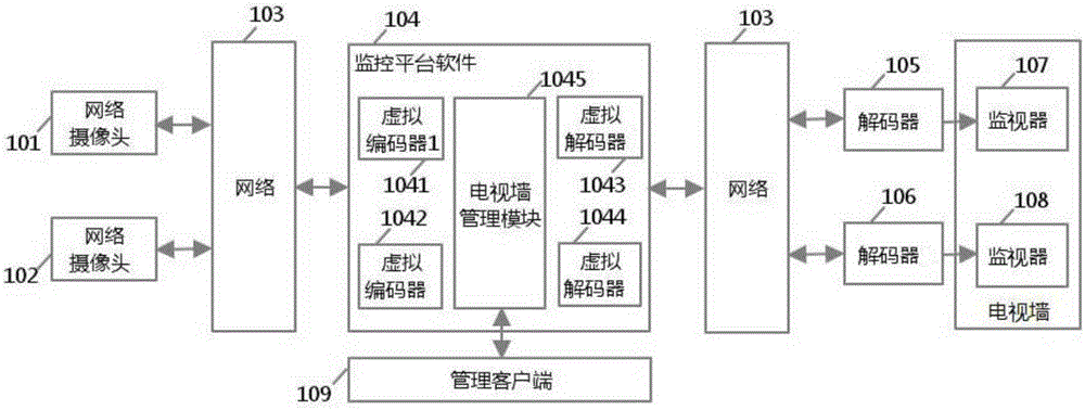
[0035] refer to figure 1 , a video monitoring system for TV wall configuration, including a monitoring terminal, a control system and a display terminal, both of the monitoring terminal and the display terminal are devices based on an IP network, and the devices can be controlled through the network.

[0036] The monitoring terminals are network cameras 101, 102, the display terminals are network-based decoders 105, 106 and video wall monitors 107, 108, and th...


PUM


Abstract

The invention discloses a video monitoring system for video-wall configuration. The video monitoring system comprises a monitoring terminal, a control system and a display terminal, wherein a management client provides a control system operation interface for a user; the monitoring terminal and the display terminal are devices based on the IP network and the devices can be controlled through the network; the control system comprises virtual coders, a video-wall management module and virtual decoders; the virtual encoders are used for being connected with and controlling the monitoring terminal; the video-wall management module is used for creating, managing and maintaining the virtual video walls and the corresponding relationship among the video wall monitoring devices, decoders and coders; the virtual decoders are used for being connected with decoders controlling the display terminal. The video monitoring system integrates a plurality of monitoring devices and display devices, and carries out centralized management and control, so that images can be viewed more conveniently through the monitoring devices.

Description

【Technical field】 [0001] The invention relates to the technical field of video monitoring, in particular to a video monitoring system used for video wall configuration. 【Background technique】 [0002] The video surveillance industry is rapidly expanding due to the increasing need for security and the development of technological innovations such as the shift to digital network-wide systems. With the advent of IP network cameras and IP video servers, and the growth of digital video recorder applications, video surveillance is moving beyond traditional security applications to include new applications such as transportation, retail, government and even home networking. This expansion greatly benefits from the idea of ​​networked distributed video surveillance, which allows all monitoring devices in the network to be managed uniformly, which makes the system more flexible. [0003] The development of distributed video monitoring leads to a wider range of monitoring equipment a...

Claims


Application Information

Patent Timeline
Patent Type & Authority Applications(China)
IPC IPC(8): H04N7/18
Inventor 夏冰余文进
Owner 武汉微创光电股份有限公司
Why Eureka
Try Eureka