
Cable lashing device and method of use thereof

A technology for tying device and cable, which is applied to the cable field of cable lacing belt, can solve the problems of cleanliness and unintentional bonding, and achieve the effect of weight saving, quick installation and low profile

Active Publication Date: 2018-08-07
DANIELS MFG CORP
View PDF11 Cites 0 Cited by
  • Summary
  • Abstract
  • Description
  • Claims
  • Application Information

AI Technical Summary

Problems solved by technology

The need to incorporate the use of adhesives or glues into the assembly method presents additional difficulties such as cleanliness of the application, inadvertent bonding of other objects and surfaces and introduction of potentially undesirable fumes and / or flammable or Incompatible Fluids or Materials

Method used


Image

  • Cable lashing device and method of use thereof
  • Cable lashing device and method of use thereof
  • Cable lashing device and method of use thereof

Examples


Embodiment Construction

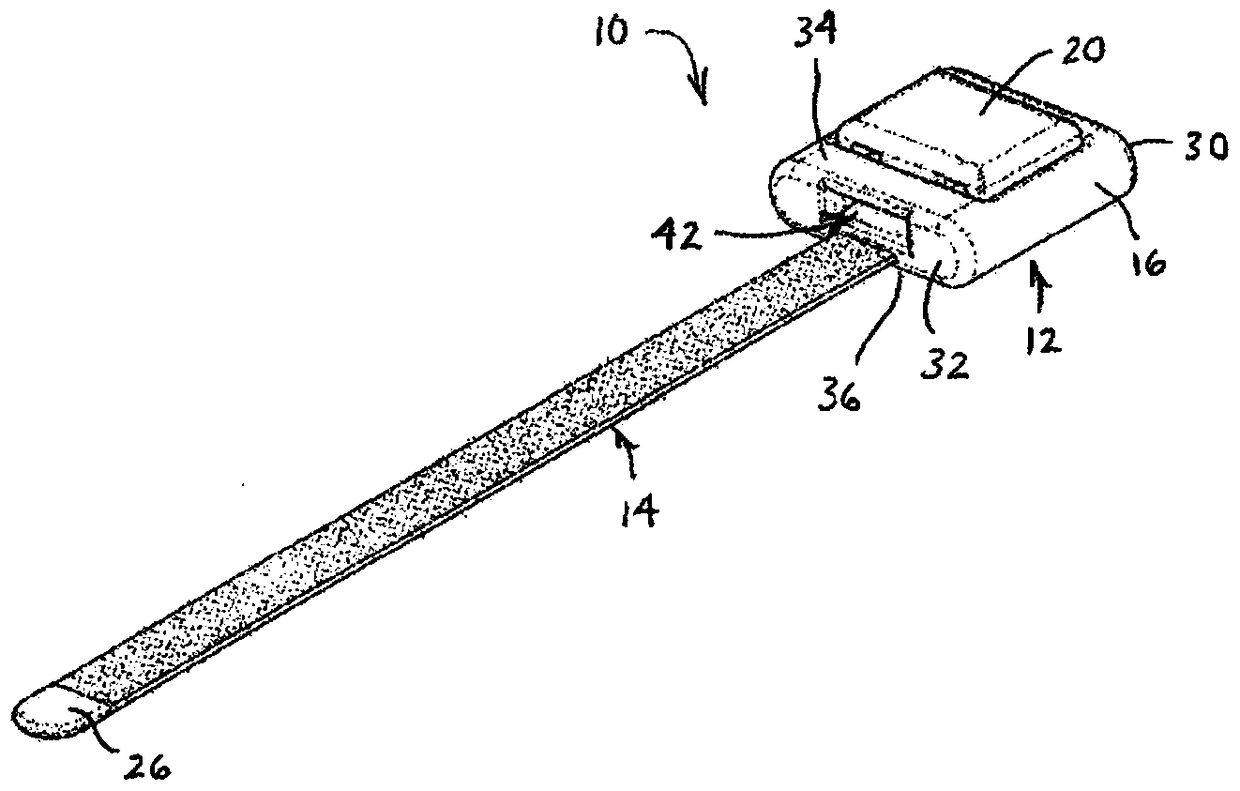
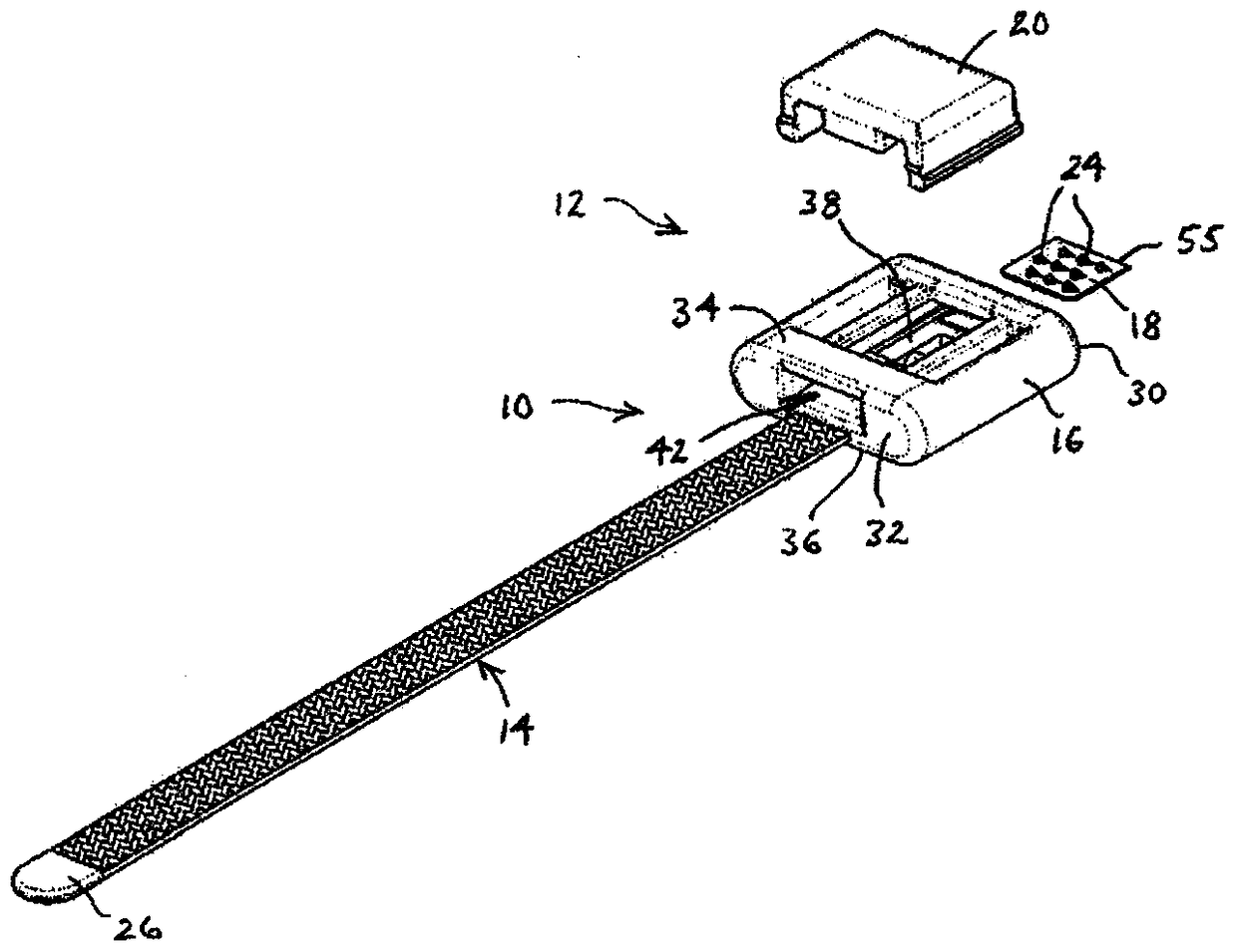
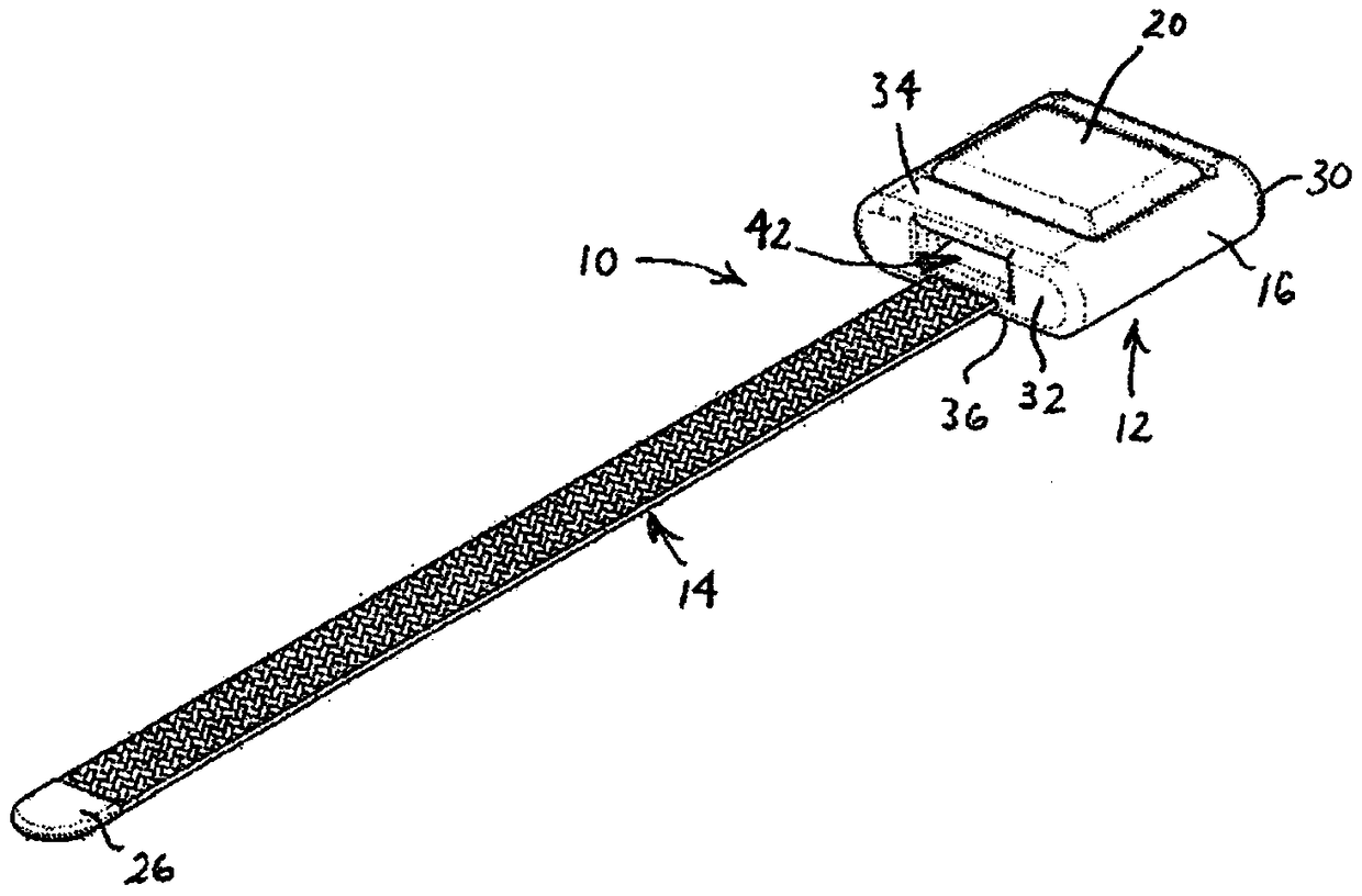
[0116] Figure 1A , 1B The cable lacing tie device of the first embodiment is described in and 2 to 11. The cable lacing tie device 10 includes a head assembly 12 and a length of cable lacing tape 14 . The head assembly 12 of this embodiment includes a formed body 16 , a retainer 18 in the form of a retainer plate, and a compression member 20 . The first portion 22 of the cable lacing strap 14 is configured to be retained in the first position within the head assembly 12, which enhances retention by having the first end insert molded in the body 16 take a tortuous path, as Figure 11 shown. A length of cable lacing tape 14 then extends from the front of the head assembly 12 . For example, the cable lacing tie device 10 can be used to tie multiple objects together, such as in image 3 A bundle B formed from a set of wires W is shown in simplified form in .

[0117] Body 16 and compression member 20 are each preferably injection molded and constructed of a material suitable...


PUM


Abstract

Cable lacing tie devices and methods of using the same are disclosed. The cable lacing tie devices include a head assembly and a cable lacing tape. The head assembly being configured to retain a first portion of the cable lacing tape within the head assembly and having a length of the cable lacing tape extending from the head assembly. The head assembly further adapted to retain a second portion of the cable lacing tape extending from the head assembly. The methods of using the cable lacing tie devices to hold together a plurality of objects with a cable lacing tie device include retaining a first portion of a cable lacing tape in a head assembly, looping the cable lacing tape around the plurality of objects and retaining a second portion of the cable lacing tape within the head assembly.

Description

[0001] Cross References to Related Applications [0002] This application is a continuation-in-part of co-pending U.S. nonprovisional patent application Serial No. 13 / 269,828, filed October 10, 2011, and claims the benefit thereof, which in turn claims filed, the benefit of U.S. Provisional Patent Application Serial No. 61 / 391,851, the entire disclosure of which is hereby incorporated by reference. Background technique [0003] The present invention relates to apparatus and methods for holding together two or more electrical wires, harnesses, cables or other objects or for connecting these objects to other structures. More particularly, the present invention relates to cable lacing tie assemblies for bundling a plurality of objects, such as wires, wire bundles, cables, or other objects, and methods of using these cable lacing tie assemblies. [0004] It is customary to group individual wires, bundles or cables having two or more wires and bundles and keep them adjacent to eac...

Claims


Application Information

Patent Timeline
Patent Type & Authority Patents(China)
IPC IPC(8): A44B99/00
CPCB65D63/1027B65D63/1045B65D63/1054B65D63/1063B65D63/1072B65D63/1081H02G3/26
Inventor 艾伦·赞陶特托马斯·彼得森斯蒂芬·莱瑟姆戴夫·弗朗奇诺祖斯坦·英格兰杰斯·查尔斯·达利
Owner DANIELS MFG CORP
Learn More