Sieve plate mechanism of hammer crusher
A hammer crusher and sieve plate technology, which is applied in the field of mining machinery, can solve the problems of difficult cleaning and easy jamming of materials on the sieve plate, and achieve the effect of increasing the effective size and avoiding the reduction of output.
- Summary
- Abstract
- Description
- Claims
- Application Information
AI Technical Summary
Problems solved by technology
Method used
Image
Examples
Embodiment Construction
[0012] The present invention will be described in further detail below by means of specific embodiments:
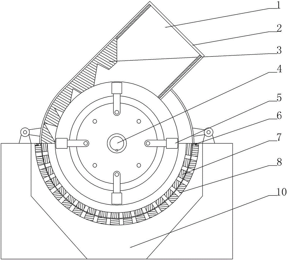
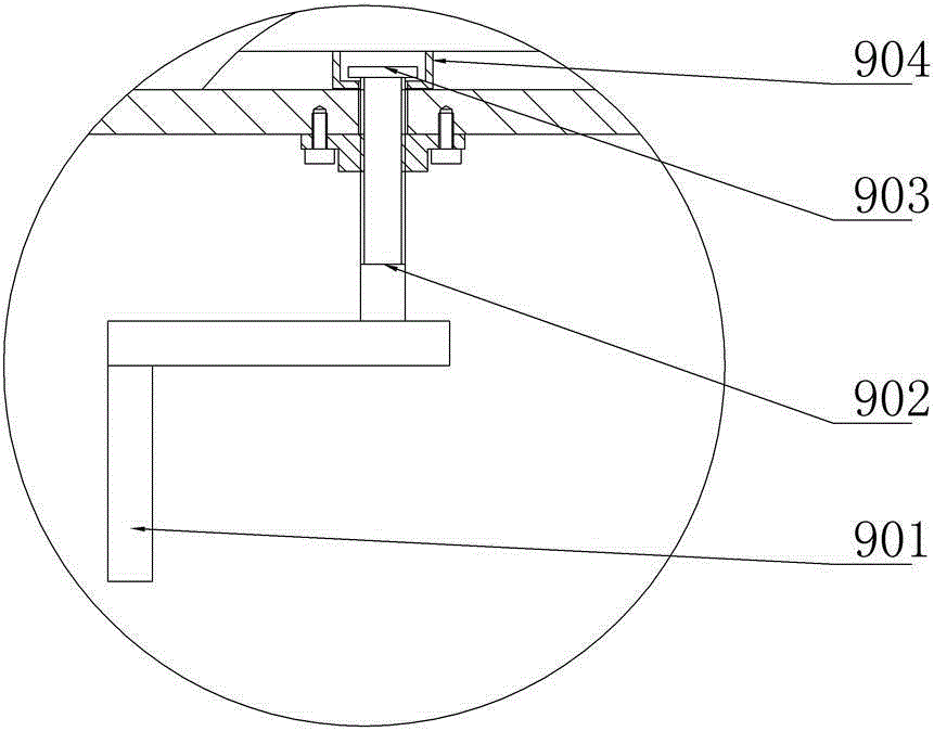
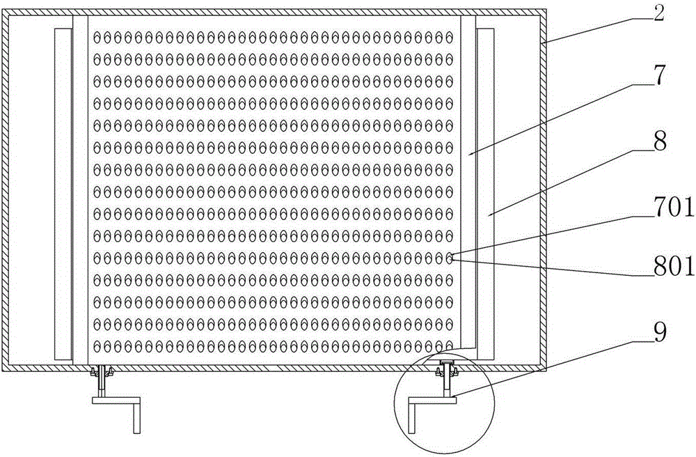
[0013] The reference signs in the drawings of the description include: feed inlet 1, box body 2, grid plate 3, rotor 4, hammerhead 5, chute 6, fixed sieve plate 7, primary sieve hole 701, movable sieve plate 8, secondary Grade sieve hole 801, push-pull device 9, rocker 901, screw rod 902, clamping plate 903, sleeve 904, discharge port 10.
[0014] as attached figure 1 As shown: the hammer crusher is composed of feed inlet 1, box body 2, grid plate 3, rotor 4, hammer head 5, fixed sieve plate 7, movable sieve plate 8, discharge port 10, etc. The hammer head of the crusher 5 is hinged with the rotor 4, and the hammer head 5 rotates at a high speed driven by the rotor 4 to obtain greater impact kinetic energy. The bulk material falls through the feed port 1 and enters the working area of the hammer crusher, where the material is impacted by the high-speed rotating hammer...
PUM
 Abstract
Description
Claims
Application Information
 - R&D
- Intellectual Property
- Life Sciences
- Materials
- Tech Scout
- Unparalleled Data Quality
- Higher Quality Content
- 60% Fewer Hallucinations
Browse by: Latest US Patents, China's latest patents, Technical Efficacy Thesaurus, Application Domain, Technology Topic, Popular Technical Reports.
© 2025 PatSnap. All rights reserved.Legal|Privacy policy|Modern Slavery Act Transparency Statement|Sitemap|About US| Contact US: help@patsnap.com


