
Continuous machining device for U-shaped heating pipes

A technology for processing equipment and heating pipes, applied in metal processing equipment, manufacturing tools, feeding devices, etc., can solve problems such as low production efficiency, affecting processing efficiency, and processing continuity limitations, and achieve high processing efficiency and processing accuracy. High, well-designed effect

Inactive Publication Date: 2016-01-06
ANHUI NINGGUO CITY TIANCHENG TECH DEV
View PDF5 Cites 4 Cited by
  • Summary
  • Abstract
  • Description
  • Claims
  • Application Information

AI Technical Summary

Problems solved by technology

Manual bending, low production efficiency, time-consuming and labor-intensive, not suitable for modern industrial production
However, most of the existing bending devices have complex structures, and each pipe processing usually requires manpower to assist feeding or unloading, which greatly affects the processing efficiency and limits the continuity of processing.
In addition, during the bending process, the bending mechanism is susceptible to wear, which affects the service life of the bending device

Method used


Image

  • Continuous machining device for U-shaped heating pipes
  • Continuous machining device for U-shaped heating pipes

Examples


Embodiment Construction

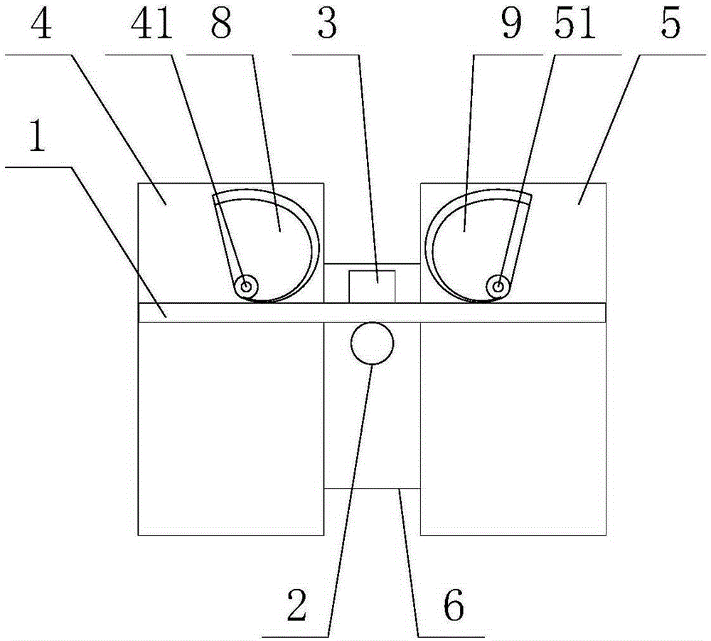
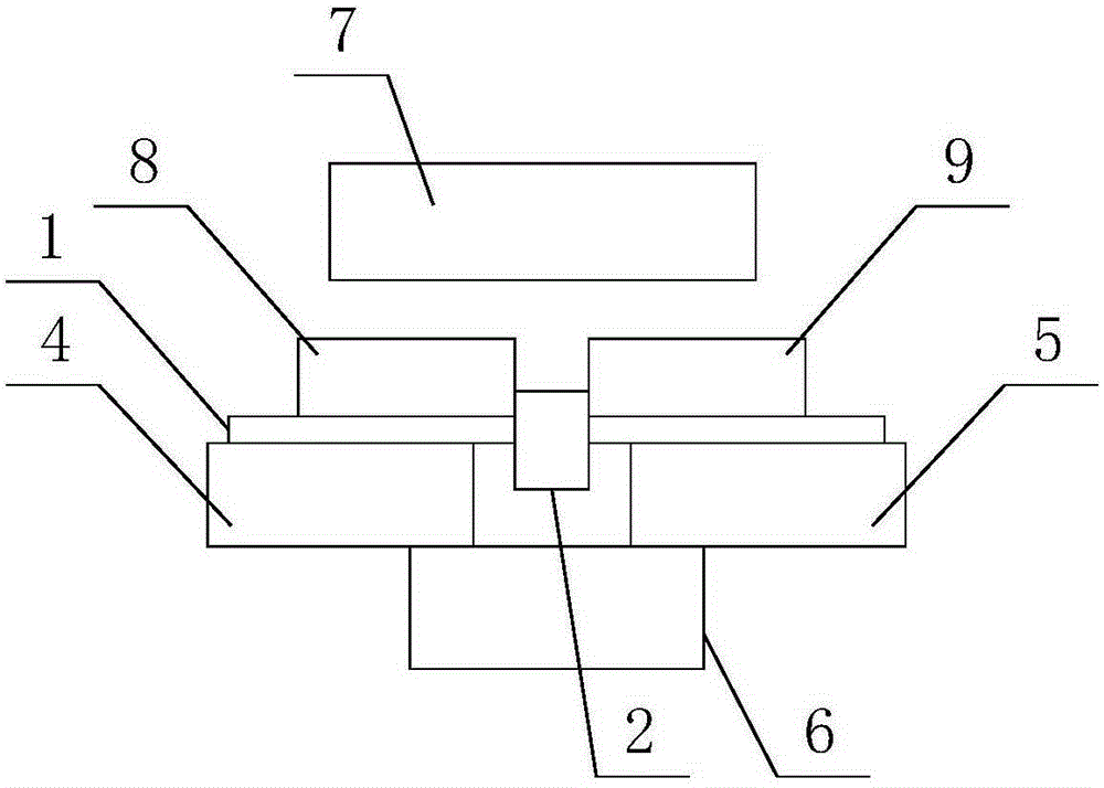
[0017] Such as figure 1 with 2 as shown, figure 1 with 2 It is a structural schematic diagram of a U-shaped heating tube continuous processing equipment proposed by the present invention, figure 2 for figure 1 Schematic diagram of the side view structure of the U-shaped heating tube continuous processing equipment.

[0018] refer to figure 1 with 2 , a U-shaped heating pipe continuous processing equipment proposed by the present invention is used for bending pipe 1, including: column 2, retaining column 3, first support platform 4, second support platform 5, material receiving trough 6, blanking Device 7, first rotary member 8, second rotary member 9, first drive device, second drive device;

[0019] The first support platform 4 and the second support platform 5 are arranged at intervals, and the two are respectively used to support the two ends of the pipe material 1 to be processed. A blanking channel is formed between the first support platform 4 and the second supp...


PUM


Abstract

The invention discloses a continuous machining device for U-shaped heating pipes. The continuous machining device comprises two supporting tables arranged in a spaced manner. A stand column and a stopping column are arranged between the two supporting tables. Rotatable rotating pieces are arranged on the two supporting tables respectively. The pipes are fed through a discharging device, so that the pipes are located between the stand column and the stopping column, and the two ends of the pipes are supported on the two supporting tables respectively. When machining is carried out, the two rotating pieces relatively rotate, and the two ends of the pipes are bent. When the two ends of the bent pipes enter the portion between the first supporting table and the second supporting table, bending is completed. Then the bent pipes enter a receiving trough through a discharging channel. When the rotating pieces rotate to restore, the discharging device carries out pipe feeding, and continuous bending of the pipes is achieved. The continuous machining device for the U-shaped heating pipes is simple in structure and reasonable in design, the pipes can be continuously bent, assisting of a worker is avoided, and the machining efficiency and the machining accuracy are high.

Description

technical field [0001] The invention relates to the field of pipe material processing, in particular to a U-shaped heating pipe continuous processing equipment. Background technique [0002] At present, in the production process of enterprises, it is often necessary to bend pipes, and the bending methods of pipes are nothing more than equipment bending and manual bending. Manpower bending, low production efficiency, time-consuming and labor-intensive, not suitable for modern industrial production. However, most of the existing bending devices have complex structures, and each pipe processing usually requires manpower to assist feeding or unloading, which greatly affects the processing efficiency and limits the continuity of processing. In addition, during the bending process, the bending mechanism is susceptible to wear, which affects the service life of the bending device. Therefore, above-mentioned problem urgently needs to solve. Contents of the invention [0003] In...

Claims


Application Information

Patent Timeline
Patent Type & Authority Applications(China)
IPC IPC(8): B21D7/00B21D7/16B21D43/02B21D43/20
Inventor 胡春国
Owner ANHUI NINGGUO CITY TIANCHENG TECH DEV
Learn More