Perforating device

A drilling device and blind hole technology, which is applied in boring/drilling, drilling/drilling equipment, and drilling templates for workpieces, etc., can solve the problems of inaccurate positioning and high cost of positioning devices, and achieve good results. Use effect, good positioning, close contact effect

Inactive Publication Date: 2016-01-06
扬州市邗江科达涂装有限公司
View PDF0 Cites 0 Cited by
  • Summary
  • Abstract
  • Description
  • Claims
  • Application Information

AI Technical Summary

Problems solved by technology

[0002] It is a common process to punch workpieces, especially for punching long workpieces at intervals. How to realize the precise positioning of each hole is particularly important. The existing positioning devices are either not very accurate in positioning. , or the cost is too high, so it needs to be further improved

Method used


Image

  • Perforating device
  • Perforating device

Examples


Embodiment Construction

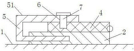
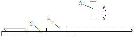
[0017] The present invention includes a frame 1 and a positioning guide rail 2 arranged on the frame 1, the frame 1 is provided with a tool 3 on the upper part of the positioning guide rail 2;

[0018] The positioning guide rail 2 is provided with hinges 4 at intervals, and the hinges 4 can interfere with the positioning guide rail 2 when rotating.

[0019] The side of the positioning guide rail 2 is provided with a blind hole inwardly, and a positioning plate 5 with a U-shaped cross section is provided to penetrate into the blind hole. The upper plate 51 of the positioning plate 5 faces the positioning guide rail 2, and the upper plate The gap formed between 51 and the positioning guide rail 2 accommodates the hinge 4 .

[0020] An elastic layer is provided on the inner wall of the upper plate 51 .

[0021] A positioning hole 6 is provided at the corresponding position of the upper plate 51 and the hinge 4 , and a positioning member 7 is provided to pass through the position...


PUM


Abstract

The invention relates to a perforating device which comprises a rack (1) and a locating guide rail (2) arranged on the rack (1). A tool (3) located on the upper portion of the locating guide rail (2) is arranged on the rack (1). Hinges (4) are arranged on the locating guide rail (2) every a certain distance, and the hinges (4) can abut against the locating guide rail (2) when rotating. The positions of the hinges are determined in advance, and during use, workpieces abut against the corresponding hinges to be perforated. Therefore, the perforated positions of the workpieces are determined through the positions of the hinges, and a good use effect is obtained after use.

Description

technical field [0001] The invention relates to a punching device, which belongs to the technical field of mechanical processing. Background technique [0002] Punching holes in workpieces is a common process, especially for punching long workpieces at intervals. How to accurately position each hole is particularly important. The existing positioning devices are either inaccurate in positioning , or the cost is too high, so it needs to be further improved. Contents of the invention [0003] The purpose of the present invention is to provide a punching device which has a simple structure and can accurately position each hole. [0004] For this reason, the technical solution adopted by the present invention is: the present invention includes a frame (1) and a positioning guide rail (2) arranged on the frame (1), and the frame (1) is provided with a positioning guide rail (2) upper cutter (3); [0005] The positioning guide rail (2) is provided with hinges (4) at intervals...

Claims


Application Information

Patent Timeline
IPC IPC(8): B23B41/00B23B47/28B26D7/01
CPCB23B41/003B23B47/28B26D7/01
Inventor 李保科李平旸张古月
Owner 扬州市邗江科达涂装有限公司
Why Eureka
Try Eureka