Collimation method of three-dimensional galvanometer and collimation system adopted by collimation method

A three-dimensional galvanometer and collimation technology, which is applied in the field of collimation systems, can solve the problems of adjusting the Z-axis galvanometer optical path center, Z-axis galvanometer center collimation difficulty and accuracy requirements, etc., to improve machining accuracy and ensure collimation sexual effect

Active Publication Date: 2016-01-06
HANS CNC SCI & TECH
View PDF8 Cites 5 Cited by
  • Summary
  • Abstract
  • Description
  • Claims
  • Application Information

AI Technical Summary

Problems solved by technology

At present, there is no special detection instrument to adjust the collimation of the optical path center of the Z-axis galvanometer, which is mainly guaranteed by the precision of machining
At present, the precision level of domestic machining is low, so the center alignment of the Z-axis galvanometer is difficult to fully meet the precision requirements of the high-precision industry

Method used


Image

  • Collimation method of three-dimensional galvanometer and collimation system adopted by collimation method
  • Collimation method of three-dimensional galvanometer and collimation system adopted by collimation method
  • Collimation method of three-dimensional galvanometer and collimation system adopted by collimation method

Examples


Embodiment Construction

[0020] In order to make the purpose, technical solution and advantages of the present invention clearer, the embodiments of the present invention will be further described below in conjunction with the accompanying drawings.

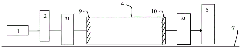
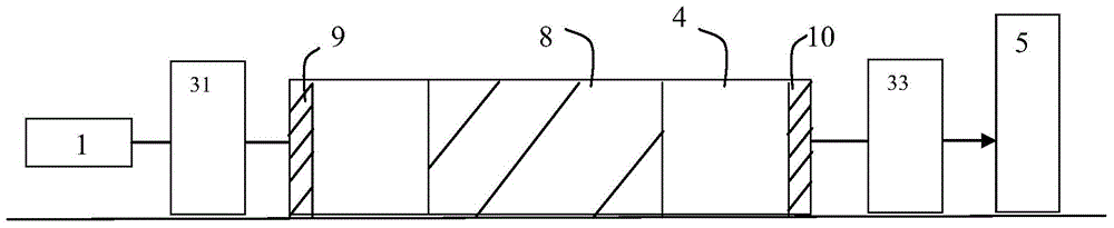
[0021] please participate figure 1 and figure 2 The collimation system of the three-dimensional vibrating mirror of the embodiment of the present invention includes a reference platform 7, a laser 1, a beam expander system 2, a first diaphragm 31, a Z-axis vibrating mirror mounting shell 4, a first Two diaphragms 33 and an observation locator 5 . The laser 1 and the beam expander system 2 are adjustably arranged on the reference platform 7 through a four-dimensional adjustment frame (not shown), and the beam expander system 2 is movably arranged on the reference platform 7 for debugging the installation of the Z-axis galvanometer Shell 4 is aligned. The first aperture 31 , the Z-axis galvanometer mounting case 4 , the second aperture 33 and the obser...


PUM


Abstract

A collimation method of a three-dimensional galvanometer comprises the following steps that two diaphragms are fixedly installed on a datum platform; a laser is installed on the datum platform and light paths emitted by the laser pass through the two diaphragms; an observation locator is installed on the datum platform, light spots of the light paths are adjusted, and the light spots are made to be located in the center of the observation locator and fixed; a beam expansion system is installed on the datum platform, the light paths are adjusted to be collimating, and the positions of the light spots on the observation locator are observed and kept unchanged; a Z-axis galvanometer installation shell is installed on the datum platform, so that the centers of a light path light inlet and a light outlet are located on the light path collimating line; and the beam expansion system is taken away, a Z-axis galvanometer is arranged in the Z-axis galvanometer installation shell, the dip angle of the Z-axis galvanometer is adjusted, the positions of the light spots on the observation locator are kept unchanged, and then the Z-axis galvanometer is fixed. The method collimates the Z-axis galvanometer installation shell and the Z-axis galvanometer, the collimation of the light path centers of the Z-axis galvanometer is ensured, and the machining precision is improved. The invention further provides a collimation system used for the collimation method of the three-dimensional galvanometer.

Description

technical field [0001] The invention relates to the field of application of laser three-dimensional (3D) vibrating mirrors, in particular to a method for collimating a 3D vibrating mirror and a collimating system adopted therefor. Background technique [0002] In the field of laser processing, the accuracy of the system using the galvanometer scanning module is mainly guaranteed by the accuracy of the galvanometer. The collimation of the center of the optical path of each axis of the galvanometer is a key factor affecting the accuracy of the galvanometer. [0003] At present, in the application of three-axis galvanometers, due to the relatively large adjustment range of the X and Y axes, it can be corrected through its own surplus angle rotation, and the products are relatively mature, and there are many adjustment methods, so the alignment of the center of the optical path can be guaranteed. However, the Z-axis vibrating mirror fixed in the laser optical path cannot adjust...

Claims


Application Information

Patent Timeline
IPC IPC(8): B23K26/042
Inventor 苏培林覃涛吕洪杰翟学涛杨朝辉高云峰
Owner HANS CNC SCI & TECH
Why Eureka
Try Eureka