
a high-gloss machine

A high-gloss machine and linear motor technology, applied in the direction of grinding frame, grinding machine parts, grinding/polishing equipment, etc., can solve the problems of poor processing effect of ordinary machines, low machine stability, rough processing surface, etc. , to achieve good processing effect, precise and controllable displacement, and stable quality

Active Publication Date: 2018-05-29
JIANGYIN WELL OPTOELECTRONICS EQUIP CO LTD
View PDF5 Cites 0 Cited by
  • Summary
  • Abstract
  • Description
  • Claims
  • Application Information

AI Technical Summary

Problems solved by technology

[0002] The disadvantages of the existing technology are that the processing effect of ordinary machines is poor, the processing surface is rough, the machine stability is not high, and the machine life is short

Method used


Image

  • a high-gloss machine
  • a high-gloss machine
  • a high-gloss machine

Examples


Embodiment Construction

[0023] Embodiments of the present invention will be further described in detail below in conjunction with the accompanying drawings.

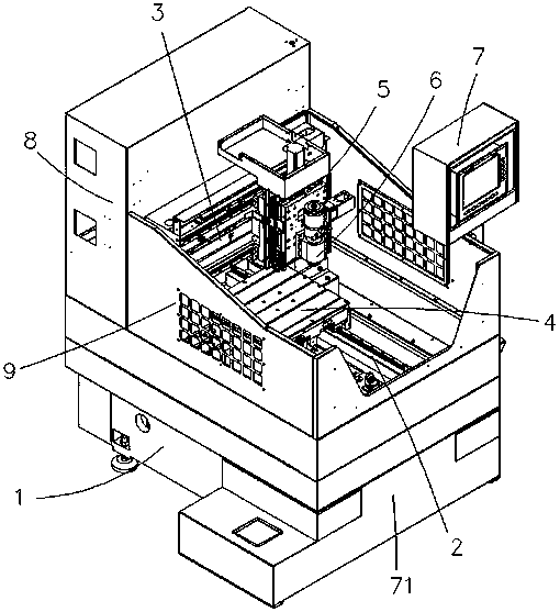
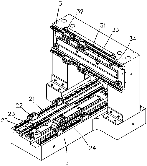
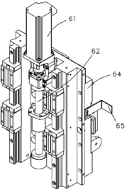
[0024] A high-gloss machine of the present invention includes a base 1, on which a main body joint is arranged, wherein: the main body joint includes a Y-direction movement base 2, and the rear part of the Y-direction movement base 2 is equipped with a gantry and a beam of the gantry There is an X-direction movement base 3 at the X-direction movement base 2, and at least one Y-direction linear track 21 extending in the Y-direction is provided on the Y-direction movement base 2. Each Y-direction linear track 21 is provided with at least one Y-direction slider 22, and the Y-direction slide The block 22 can slide on the Y-direction linear track 21, and a workbench device 4 is fixed on the Y-direction slider 22. The upper surface of the workbench device 4 places the workpiece, and the lower part is provided with a workbench linear motor coil 41, and...


PUM


Abstract

The invention discloses a polishing machine which comprises a base. A main body combining piece is arranged on the base. The main body combining piece comprises a Y-direction movement matrix, an X-direction movement matrix, a Z-direction movement matrix and a tool bit part. A workbench device is arranged on the Y-direction movement matrix. A linear motor coil is arranged below the workbench device. Y-direction magnetic plates are arranged in the position, corresponding to the workbench linear motor coil, of the Y-direction movement matrix. The Z-direction movement matrix is arranged on the X-direction movement matrix. The Z-direction movement matrix is provided with a linear motor coil. X-direction magnetic plates are arranged on the X-direction movement matrix. A machine head device comprises a tool installing station which right faces the upper surface of the workbench device. The polishing machine has the advantages of being good in machining effect and stable in quality. Meanwhile, electromagnetic transmission has the characteristic of being free of contact and abrasion, so that the service life of the polishing machine is longer than that of an ordinary polishing machine.

Description

technical field [0001] The invention relates to the technical field of metal surface processing, in particular to a machine for processing a mirror effect on a metal surface, specifically, a high-gloss machine. Background technique [0002] The disadvantages of the prior art are that the processing effect of ordinary machines is poor, the processing surface is rough, the machine stability is not high, and the machine life is short. Now aiming at the defects of the prior art, a high-gloss machine with good processing effect, stable quality and long service life is especially needed, so as to solve the above-mentioned problems. Contents of the invention [0003] The present invention proposes a new type of high-gloss machine based on the shortcomings of the above-mentioned prior art. The high-gloss machine has the advantages of good processing effect, stable quality and long service life. [0004] The technical solution adopted by the present invention to solve the problems...

Claims


Application Information

Patent Timeline
Patent Type & Authority Patents(China)
IPC IPC(8): B24B41/02B24B47/02B24B51/00
CPCB24B41/02B24B47/02B24B51/00
Inventor 焦昌富蔡翔吴莉国
Owner JIANGYIN WELL OPTOELECTRONICS EQUIP CO LTD
Learn More