Vibration type conveying device

A conveying device and vibrating technology, which is applied in the field of vibrating conveying devices, can solve problems such as inability to fully adjust the conveying speed of conveyed objects, difficult adjustment operations, and unstable vibration patterns.

Active Publication Date: 2016-01-06
DAISHIN CO LTD
View PDF5 Cites 4 Cited by
  • Summary
  • Abstract
  • Description
  • Claims
  • Application Information

AI Technical Summary

Problems solved by technology

Therefore, there is a problem that the conveying speed of the conveyed object cannot be adjusted sufficiently without changing the inclination angle of the anti-vibration leaf spring to a certain extent, but when the above-mentioned inclination angle is greatly changed, the vibration pattern becomes unstable
[0014] In addition, in this method, since the support form of the driving vibration system composed of the conveying body and the weight connected via the driving plate spring changes greatly in the conveying direction, it is necessary to properly set the conveyance of the entire conveying body. When balancing the state, such as the uniformity of the conveying speed on the entire conveying path or the variation of the conveying speed in the conveying direction, the balance of the front and rear anti-vibration leaf springs must be considered, so the actual adjustment work is difficult in most cases.
[0015] In addition, in the method of adjusting the inclination angle of the plate spring for anti-vibration as described above, although the posture or height of the transport body can be kept almost constant, it is unavoidable that the posture or height will be changed due to the installation or removal of bolts or screws. Minor deviations occur. Therefore, in order to cope with the situation that the accuracy required for the posture or height of the conveyed body has gradually increased with the miniaturization of the conveyed objects in recent years, it is impossible to omit the readjustment of the posture or height in the same way as the above method. complex work

Method used


Image

  • Vibration type conveying device
  • Vibration type conveying device
  • Vibration type conveying device

Examples


Embodiment Construction

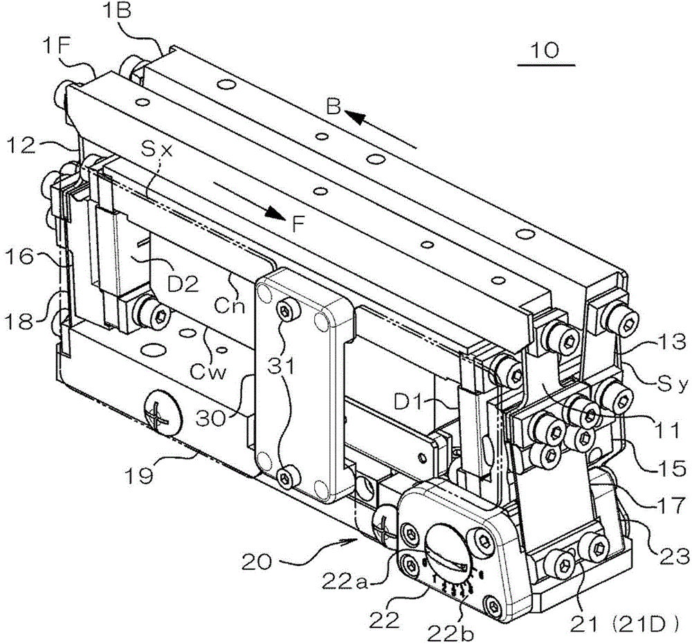
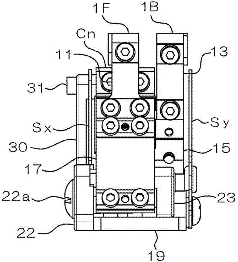
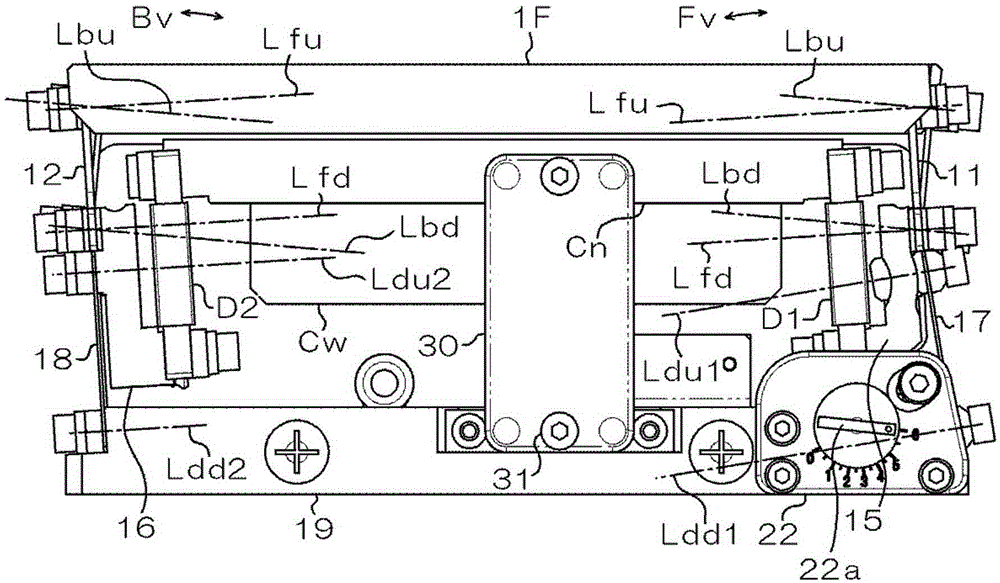
[0063] Next, embodiments of the present invention will be described in detail with reference to the drawings. figure 1 It is a perspective view of this embodiment, figure 2 is a front view of this embodiment, image 3 is a left side view showing the state with the side cover removed, Figure 4 It is a left side view showing the state after further removing the supporting and fixing parts, Figure 5 is another stereogram, Image 6 is a right side view showing the state with the side cover removed, Figure 7 is another perspective view with the side cover panels removed.

[0064] The vibratory conveying device 10 of the present embodiment can attach a conveying body (not shown) having a conveying path. The transport body has a groove-shaped transport path corresponding to the shape and size of the transport object (for example, an electronic device). In the illustrated example, the vibratory conveying device 10 has a first tank 1F and a second tank 1B, wherein a first con...


PUM


Abstract

The invention provides a vibration type conveying device. According to the vibration type conveying device, a conveying state can be regulated easily along a conveying path. The vibration type conveying device is provided with a conveying body with the conveying path, a pair of drive plate springs (11) and (12), a pair of connecting bodies (15) and (16), a pair of piezoelectric drive bodies (D1) and (D2), coupling parts (Cn) and (Cw), a pair of anti-vibration plate springs (17) and (18) and a spring angle regulating mechanism (20). The pair of drive plate springs (11) and (12) are provided with supporting conveying bodies on the front position and the rear position in the conveying direction (F) of the conveying path respectively; the pair of connecting bodies (15) and (16) are respectively arranged on the front position and the rear position in the conveying direction, and are connected with a conveying body through the pair of drive plate springs respectively; the pair of piezoelectric drive bodies (D1) and (D2) are arranged on front position and rear position in the conveying direction respectively, and one end of each piezoelectric drive body is connected with the corresponding connecting body; by virtue of the coupling parts (Cn) and (Cw), the other ends of the pair of the piezoelectric drive bodies are connected with each other; the pair of anti-vibration plate springs (17) and (18) respectively support the pair of the connecting bodies on the front position and the rear position in the conveying direction on an arranging surface; the spring angle regulating mechanism (20) is arranged to be capable of regulating the inclination angle of anti-vibration plate springs at any one side in the front portion and the back portion of the conveying direction.

Description

technical field [0001] The present invention relates to a vibrating conveying device, in particular to a mechanism for adjusting the conveying state of conveyed objects. Background technique [0002] Conventionally, there is known a vibrating conveying device for supplying electronic components and the like to an inspection device and the like while being aligned on a conveying path in a manufacturing facility. In this case, since the processing speed of the conveyed object such as the inspection device arranged on the downstream side of the conveying path is constant, at the supply end of the conveying path of the vibrating conveying device, it is necessary to adjust the speed with the downstream side. The conveyed material is supplied at a speed corresponding to the processing speed of the supply target device. [0003] Here, if the supply speed of the conveyed object is lower than the processing speed of the supply target device, the processing efficiency of the entire m...

Claims


Application Information

Patent Timeline
IPC IPC(8): B65G27/10B65G27/08
Inventor 原顺一折桥英树皆川恭弘
Owner DAISHIN CO LTD
Why Eureka
Try Eureka