Sheet inserting machine

A inserting machine and inserting technology, applied in the direction of conveyors, vibrating conveyors, conveyor objects, etc., can solve the problems of low production efficiency, low degree of automation, single rotor insertion, etc., to meet the accuracy requirements and production efficiency Enhanced, angle-accurate and stable effects

Inactive Publication Date: 2016-01-06
NINGBO INST OF TECH ZHEJIANG UNIV ZHEJIANG
View PDF5 Cites 8 Cited by
  • Summary
  • Abstract
  • Description
  • Claims
  • Application Information

AI Technical Summary

Problems solved by technology

However, similar inserting machines in the prior art have a common defect, that is, they only realize the automation of inserting inserts, but cannot realize the automation of rotor installation, and the installation of rotors still requires manual installation, which has low degree of automation, poor continuity, and production. still less efficient
In fact, the problem of automatic loading and installation of the rotor is a technical problem that has plagued technicians in the industry for many years, because the rotor is generally a plastic part, light in weight, and there are many installation grooves on the outer peripheral surface of the rotor, requiring

Method used


Image

  • Sheet inserting machine
  • Sheet inserting machine
  • Sheet inserting machine

Examples


Embodiment Construction

[0029] The present invention will be further described below in conjunction with the accompanying drawings and specific embodiments.

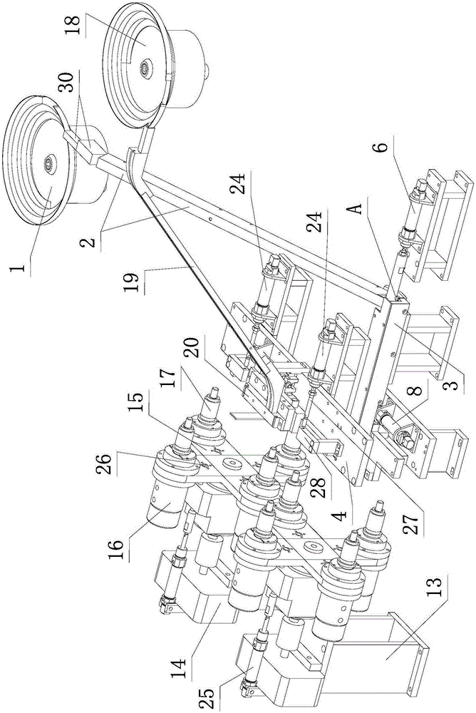
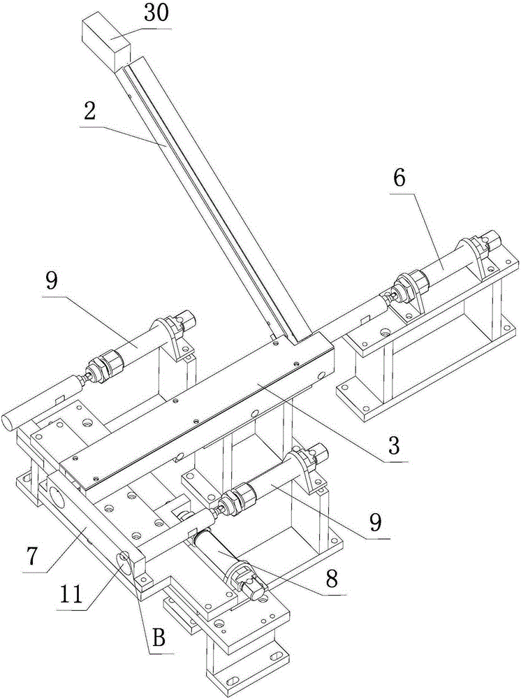
[0030] like figure 1 , figure 2 , image 3 , Figure 4 , Figure 5 , Figure 6 , Figure 7 , Figure 8 , Figure 9 , Figure 10 , Figure 11 , Figure 12 As shown, the inserting machine of the present invention includes a rotor automatic feeding device, two left and right symmetrical station switching devices, an inserting automatic feeding device and two left and right inserting cylinders 24 .

[0031] The rotor automatic feeding device includes a rotor vibrating plate 1, a radially inclined feeding channel 2, an axial horizontal feeding channel 3, and a pushing cylinder 6 for pushing the rotor 5 located at the head end of the axial horizontal feeding channel 3 to the end , the first swinging plate 7 perpendicular to the axial horizontal feeding channel 3, the first swinging cylinder 8 and two feeding cylinders 9 on the left and ri...


PUM


Abstract

The invention discloses a sheet inserting machine which comprises an automatic rotor feeding device, two station switching devices in left-right symmetry, an automatic inserting sheet feeding device, a left sheet inserting cylinder (24) and a right sheet inserting cylinder (24). The automatic rotor feeding device comprises a rotor vibration disc (1), a radial inclined feeding channel (2), an axial horizontal feeding channel (3), a pushing cylinder (6), a first swing plate, a first swing cylinder (8), a left feeding cylinder and a right feeding cylinder, wherein the pushing cylinder (6) is used for pushing rotors at the head end of the axial horizontal feeding channel (3) to the tail end of the axial horizontal feeding channel (3), and the first swing plate is perpendicular to the axial horizontal feeding channel (3). The automatic inserting sheet feeding device comprises an inserting sheet vibration disc (18), an inclined inserting sheet feeding channel (19), a second swing plate (20) perpendicular to the inclined inserting sheet feeding channel (19), and a second swing cylinder driving the second swing plate (20). The sheet inserting machine is high in automation degree, continuity and production efficiency.

Description

technical field [0001] The invention relates to the mechanical field, in particular to a chip inserting machine for inserting a chip into a rotor installation groove. Background technique [0002] In industrial manufacturing fields such as automobiles and home appliances, it is often necessary to insert inserts into the rotor, such as inserting spacers on the motor rotor, or inserting vanes on the rotor of the vane pump, or inserting timing pieces on the rotor of the timer ,Wait. The rotor is provided with a central hole along the axial direction, and the rotor has a plurality of installation grooves evenly distributed along the circumferential direction. The most traditional method is to manually insert the metal inserts one by one into the corresponding installation slots of the plastic rotor, but this method is inefficient and obviously not suitable for mass industrial production. [0003] In the prior art, someone has also developed a chip inserting machine that relies...

Claims


Application Information

Patent Timeline
IPC IPC(8): B65G47/14B65G27/02B65G47/82
Inventor 张学昌申梓刚敖开才韩俊翔杨仁民包颖杰徐丰翎徐方伟
Owner NINGBO INST OF TECH ZHEJIANG UNIV ZHEJIANG
Why Eureka
Try Eureka