Rotor automatic feeding device of inserting machine

An automatic feeding and chip inserting machine technology, applied in the field of machinery, can solve the problems of high precision of rotor insertion angle, low production efficiency, low degree of automation, etc., achieve continuous fully automatic feeding, meet precision requirements, Angle-accurate and stable effect

Inactive Publication Date: 2017-06-30
NINGBO INST OF TECH ZHEJIANG UNIV ZHEJIANG
View PDF5 Cites 2 Cited by
  • Summary
  • Abstract
  • Description
  • Claims
  • Application Information

AI Technical Summary

Problems solved by technology

However, similar inserting machines in the prior art have a common defect, that is, they only realize the automation of inserting inserts, but cannot realize the automation of rotor installation, and the installation of rotors still requires manual installation, which has low degree of automation, poor continuity, and production. still less efficient
In fact, the problem of automatic loading and installation of the rotor is a technical problem that has plagued technicians in the industry for many years, because the rotor is generally a plastic part, light in weight, and there are many installation grooves on the outer peripheral surface of the rotor, requiring the center hole of the rotor Precisely fit on the fixed shaft, and the accuracy of the rotor’s fitting angle is very high, because the axial direction of the mounting groove on the rotor must completely coincide with the insertion track of the insertion piece, otherwise the insertion piece will not be able to be inserted, and now Technical mechanical equipment naturally cannot guarantee that a single rotor can be inserted onto the fixed shaft at such an accurate angle, and single feeding cannot be guaranteed, let alone batch continuous and fast feeding of multiple rotors. Therefore, the existing Technology can only adopt inefficient manual rotor installation

Method used


Image

  • Rotor automatic feeding device of inserting machine
  • Rotor automatic feeding device of inserting machine
  • Rotor automatic feeding device of inserting machine

Examples


Embodiment Construction

[0026] The present invention will be further described below in conjunction with the accompanying drawings and specific embodiments.

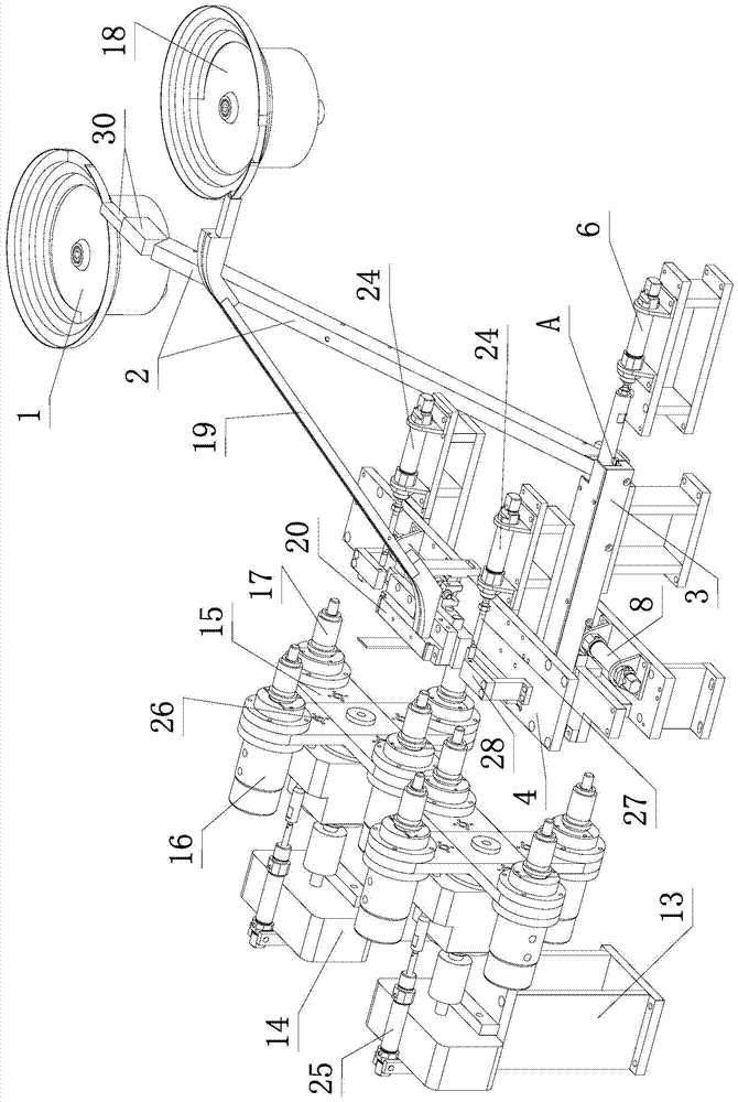
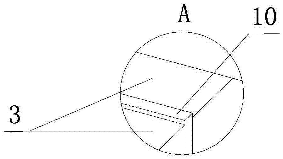
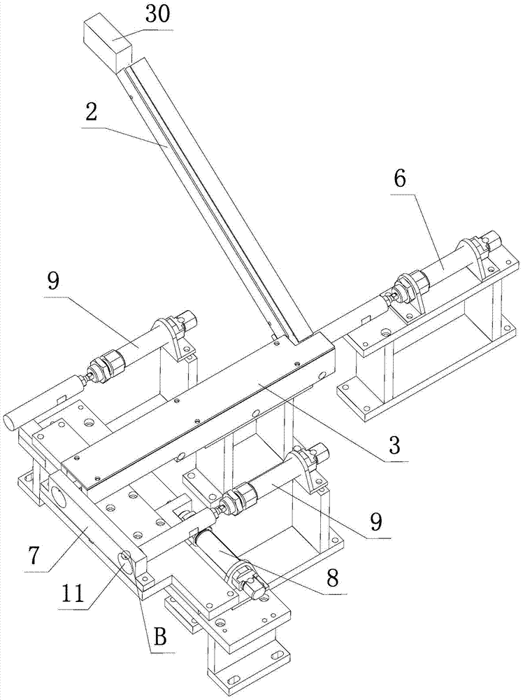
[0027] Such as figure 1 , figure 2 , image 3 , Figure 4 , Figure 5 , Figure 6 , Figure 7 , Figure 8 , Figure 9 , Figure 10 , Figure 11 , Figure 12 As shown, the rotor automatic feeding device of the chip inserting machine of the present invention includes a rotor vibrating plate 1, a radially inclined feed channel 2, an axial horizontal feed channel 3, and is used to place the 3 heads located in the axial horizontal feed channel. The rotor 5 at the end pushes the cylinder 6 to the end, the first swing plate 7 perpendicular to the axial horizontal feed channel 3, the first swing cylinder 8 and the left and right two feeding cylinders 9. The rotor vibrating plate 1 is a fairly mature existing technology, that is, a spirally rising disc is set inside the rotor vibrating disc 1, the width of the end of the disc is equal to the...


PUM


Abstract

The invention discloses an automatic rotor feeding device for a sheet inserting machine, which comprises a rotor vibrating plate, a radially inclined feeding path (2), an axially horizontal feeding path (3), and a (3) The pushing cylinder (6) from the rotor at the head end to the end, the first swinging plate (7) perpendicular to the axial horizontal feeding channel (3), the first swinging cylinder (8) and the left and right two feeders Cylinder (9); the disc end of the rotor vibrating plate communicates with the upper end of the radially inclined feeding channel (2); the lower end of the radially inclined feeding channel (2) communicates with the head end of the axially horizontal feeding channel (3); the second A swing plate (7) is connected with the piston rod of the first swing cylinder (8), and two round holes (11) on the left and right are arranged on the first swing plate (7). The rotor automatic feeding device of the inserting machine can realize batch continuous automatic feeding of the rotors.

Description

technical field [0001] The invention relates to the field of machinery, in particular to an automatic rotor feeding device for inserting inserts into rotor mounting slots. Background technique [0002] In industrial manufacturing fields such as automobiles and home appliances, it is often necessary to insert inserts into the rotor, such as inserting spacers on the motor rotor, or inserting vanes on the rotor of the vane pump, or inserting timing pieces on the rotor of the timer ,Wait. The rotor is provided with a central hole along the axial direction, and the rotor has a plurality of installation grooves evenly distributed along the circumferential direction. The most traditional method is to manually insert the metal inserts one by one into the corresponding installation slots of the plastic rotor, but this method is inefficient and obviously not suitable for mass industrial production. [0003] In the prior art, someone has also developed a chip inserting machine that r...

Claims


Application Information

Patent Timeline
Patent Type & Authority Patents(China)
IPC IPC(8): B65G47/14B65G47/82
Inventor 张学昌吴占超申梓刚敖开才包颖杰徐丰翎徐方伟
Owner NINGBO INST OF TECH ZHEJIANG UNIV ZHEJIANG
Why Eureka
Try Eureka