Electric control cabinet lifting device for escalator

A technology for electrical control cabinets and escalators, applied in escalators, transportation and packaging, etc., can solve the problems of low operation efficiency, high maintenance work intensity, accompanying danger, etc., and achieve the effect of improving operation efficiency and reducing manpower input

Active Publication Date: 2016-11-16
HANSON LIFT (SUZHOU) CO LTD
View PDF7 Cites 0 Cited by
  • Summary
  • Abstract
  • Description
  • Claims
  • Application Information

AI Technical Summary

Problems solved by technology

[0003] Since the weight of the electrical control cabinet of the escalator is about 80-100 kg, it is very troublesome to lift (carry) the heavy electrical control cabinet 2 from the upper machine room of the escalator to the floor or floor board, specifically as follows: First, it requires a lot of manpower, because it is difficult to complete it with only one person; second, the operation efficiency is low; third, the work intensity of the maintenance worker is high; fourth, it is accompanied by danger, or damage to the maintenance worker's limbs, or damage to the electrical control cabinet
[0004] Invention patent authorization announcement number CN102701059B (the patent was proposed by the applicant) made up for the above-mentioned shortcomings, and objectively fulfilled the technical effect recorded in paragraph 0014 of its description, but there are still the following shortcomings: First, due to the connection between the fixed seat and the rotary A pair of power-assist mechanisms between the frames uses springs in an exposed state, and the Achilles heel of the springs is easy to fatigue, so after a limited number of uses, it loses its elastic effect and cannot achieve the desired power-assist effect; The distance difference between self-extension and contraction is limited, so it is still relatively laborious to lift the electrical control cabinet

Method used


Image

  • Electric control cabinet lifting device for escalator
  • Electric control cabinet lifting device for escalator
  • Electric control cabinet lifting device for escalator

Examples


Embodiment Construction

[0022] In order to enable the examiners of the patent office, especially the public, to understand the technical essence and beneficial effects of the present invention more clearly, the applicant will describe in detail the following in the form of examples, but none of the descriptions to the examples is an explanation of the solutions of the present invention. Any equivalent transformation made according to the concept of the present invention which is merely formal but not substantive shall be regarded as the scope of the technical solution of the present invention.

[0023] In the following descriptions, all concepts involving up, down, left, right, front and rear directionality or azimuth are for the position state of the picture being described, and the purpose is to facilitate the public’s understanding. Therefore, it cannot be understood as a special limitation on the technical solution provided by the present invention.

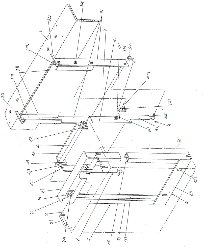
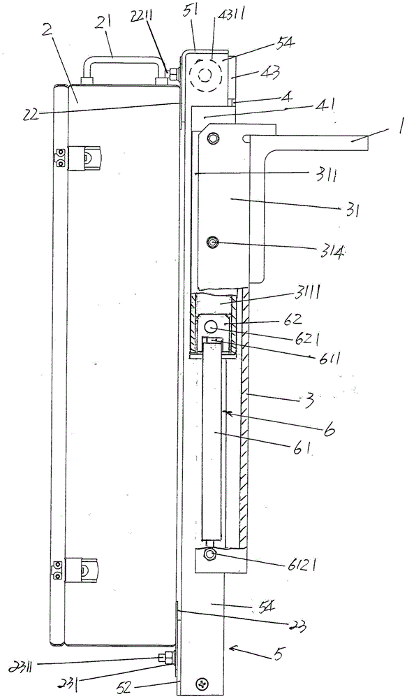
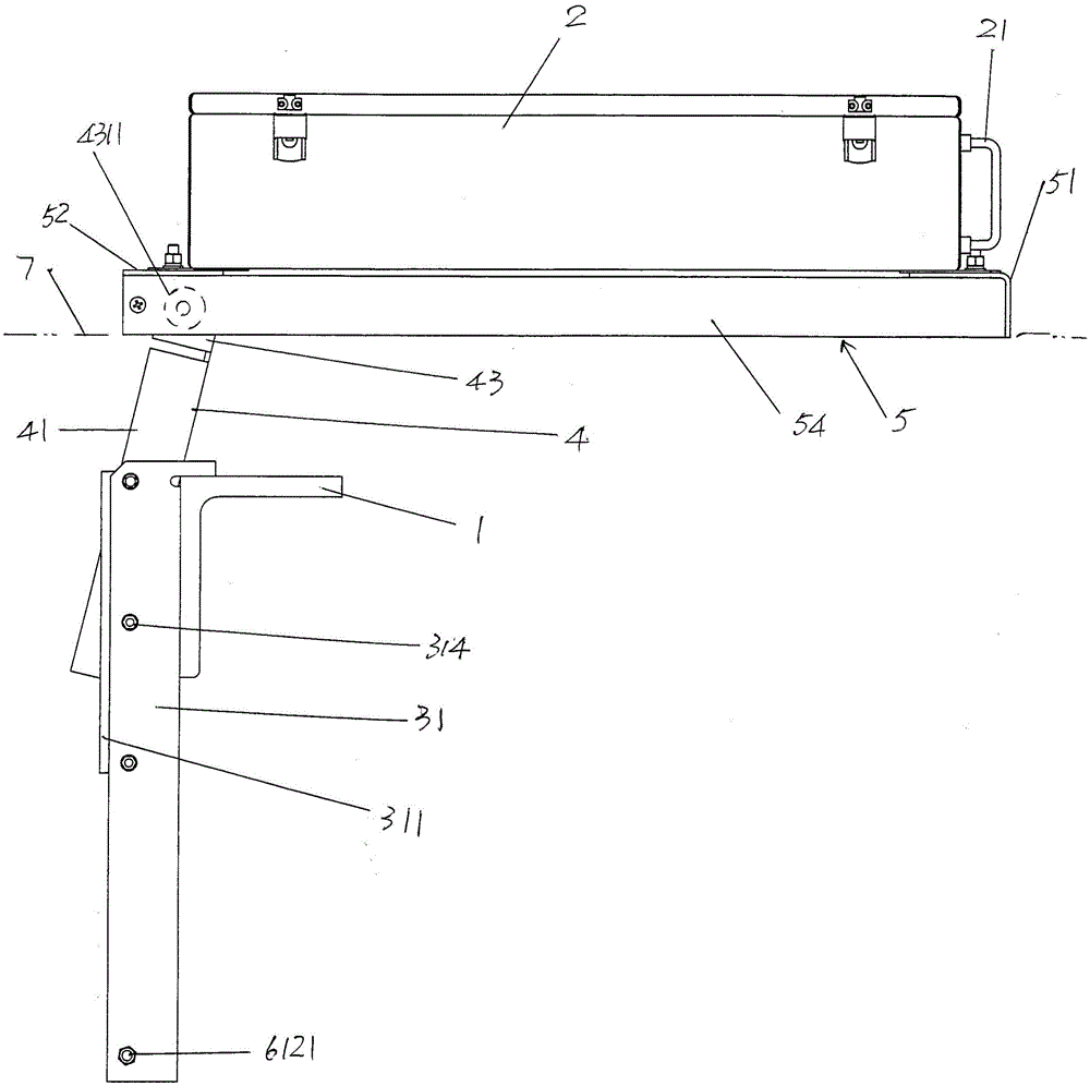
[0024] See figure 1 , shows the truss 1 and...


PUM


Abstract

The invention relates to an electrical control cabinet lift device for an escalator, belonging to the technical field of inclined escalators. The escalator comprises a truss and an electrical control cabinet. The electrical control cabinet lift device comprises a reversing frame supporting plate, a reversing frame, a bracket and a pair of power-assisted mechanisms, wherein the reversing frame supporting plate is fixed on one side, facing to the electrical control cabinet, of the truss; the reversing frame corresponds to the reversing frame supporting plate and is matched with the reversing frame supporting plate in a sliding manner, and the bracket is matched with the reversing frame in a sliding manner; the power-assisted mechanisms are connected between the reversing frame supporting plate and the reversing frame, and the electrical control cabinet is fixed on the bracket. The electrical control cabinet lift device is characterized in that each power-assisted mechanism comprises an acting cylinder and a sliding block; an acting cylinder column of the acting cylinder is upward and connected with the reversing frame, and the lower part of the acting cylinder is connected with the lower part of the reversing frame supporting plate; the sliding block and the acting cylinder column are coaxially connected to the reversing frame and matched with the reversing frame supporting plate. The electrical control cabinet lift device has the advantages that the good assisted-powder effect is enduringly developed, the manpower input is reduced, the operation efficiency is improved, the operating strength of inspection and protection personnel is reduced, and the safety is ensured.

Description

technical field [0001] The invention belongs to the technical field of inclined escalators, and in particular relates to a lifting device for an electric control cabinet of an escalator, which is arranged on a truss of an escalator or a sidewalk, and is used for leading in or leading out (lifting) the electric control cabinet. Background technique [0002] As known in the industry, the operation of the escalator is controlled by the electrical control cabinet (also called the electrical control box, the same below). The electrical control cabinet is installed under the platform on the top of the escalator and fixed to the escalator frame, that is, the truss. See Figure 5 ,Should Figure 5 The truss 1 of the escalator in the prior art is illustrated, and the electric control cabinet 2 is fixed with the truss 1 with bolts. When it is necessary to maintain and overhaul the electrical control cabinet 2, the overhauler removes the bolts to separate the electrical control cabinet...

Claims


Application Information

Patent Timeline
Patent Type & Authority Patents(China)
IPC IPC(8): B66B23/00
Inventor 仲浩陈富春朱学明
Owner HANSON LIFT (SUZHOU) CO LTD
Why Eureka
Try Eureka