Safety rail support rod of transformer substation

A technology of safety fence and support rod, applied in the field of support rod, can solve the problems of falling rod of support rod, loss of safety protection of staff, increase of workload of operation and maintenance personnel, etc., and achieve the effect of preventing accidental entry into the area with point and simple structure.

Active Publication Date: 2016-01-06
SUIHUA POWER SUPPLY COMPANY OF STATE GRID HEILONGJIANG ELECTRIC POWER COMPANY +1
View PDF11 Cites 3 Cited by
  • Summary
  • Abstract
  • Description
  • Claims
  • Application Information

AI Technical Summary

Problems solved by technology

[0004] The present invention solves the phenomenon that the existing substation safety fence support often has the phenomenon that the support rod is inverted because the support is not placed firmly, which makes the staff l...

Method used


Image

  • Safety rail support rod of transformer substation
  • Safety rail support rod of transformer substation
  • Safety rail support rod of transformer substation

Examples


specific Embodiment approach 1

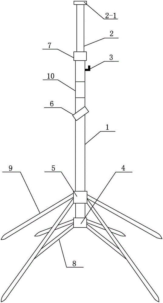
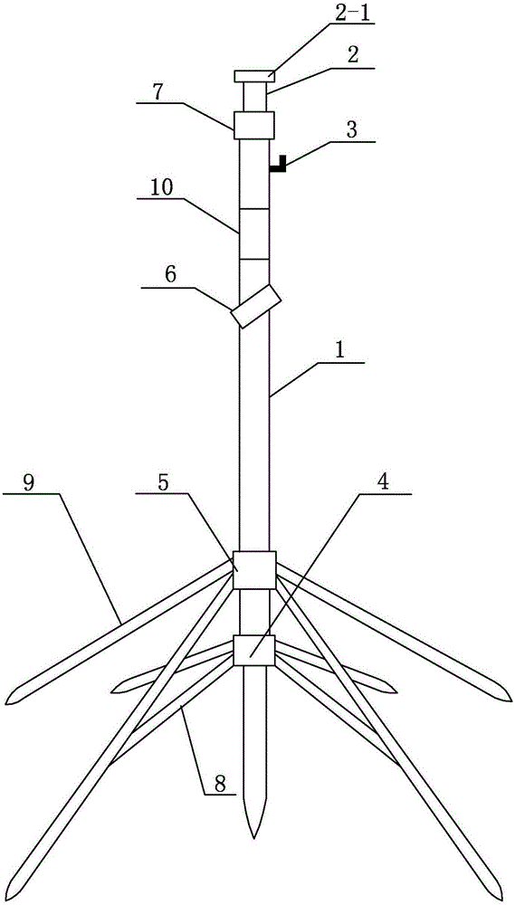
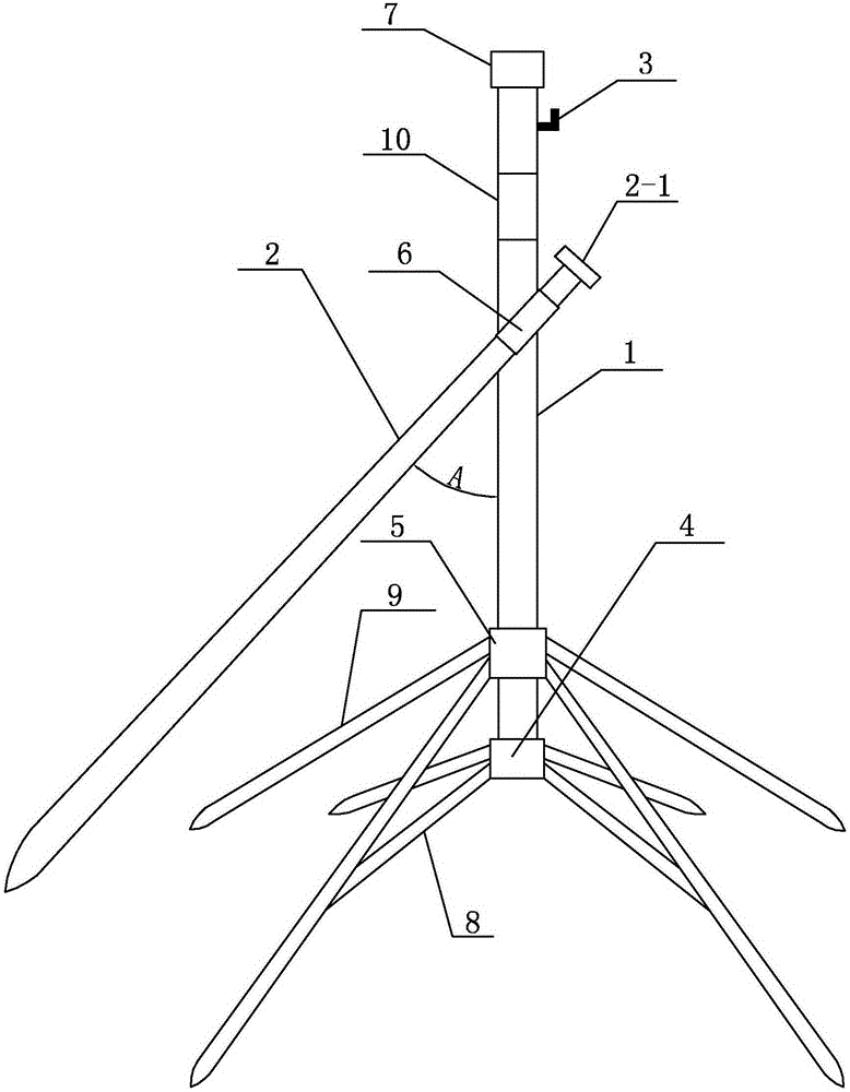
[0009] Specific implementation mode one: combine figure 1 , figure 2 and image 3 Describe this embodiment, a substation safety fence support rod described in this embodiment includes a main frame rod 1, a fixed rod 2, a fence hook 3, a first collar 4, a second collar 5, a lock 6, a first bracket And the second bracket, the main frame rod 1 is hollowly arranged, the bottom of the main frame rod 1 is sequentially set with the first collar 4 and the second collar 5, and the outer wall of the first collar 4 is fixed with the first bracket , the outer wall of the second collar 5 is fixed with a second bracket, the first bracket and the second bracket are fixed on the ground, the upper part of the outer wall of the main frame rod 1 is provided with a fence hook 3, and the lock catch 6 is arranged on the main frame The upper part of the outer wall of the rod 1, when the soil quality of the job site is not frozen: the fixed rod 2 is set in the main frame rod 1, and the lower part ...

specific Embodiment approach 2

[0011] Specific implementation mode two: combination figure 1 , figure 2 and image 3 To illustrate this embodiment, the substation safety fence support rod described in this embodiment further includes a limit ring 8 , which is sleeved on the upper part of the outer wall of the main frame rod 1 . So set, the top of fixed rod 2 is provided with stopper 2-1, and the bottom of fixed rod 2 is inserted in the soil, prevents the top of fixed rod 2 from inserting in the main frame rod 1 and causes the generation of support rod inconveniently pulling out soil situation. Other compositions and connections are the same as those in the first embodiment.

specific Embodiment approach 3

[0012] Specific implementation mode three: combination figure 1 , figure 2 and image 3 To illustrate this embodiment, the first support in this embodiment includes a plurality of first support rods 8, and the plurality of first support rods 8 are evenly distributed and fixed on the outer wall of the first collar 4 to form an umbrella shape, and each first Support rod 8 telescopic settings. In this way, the lower parts of the plurality of first support rods 8 can be inserted into the soil when the soil quality of the job site is not frozen. The cooperation makes the support of the main frame rod 1 more stable, and each first support rod 8 can be telescopically arranged for convenient storage. Other compositions and connections are the same as those in Embodiment 1 or Embodiment 2.


PUM


Abstract

The invention relates to a safety rail support rod of a transformer substation. The safety rail support rod aims at solving the problems that an existing safety rail support of a transformer substation usually falls off due to the fact that a support is placed unstably, staff lose safety protection, large potential safety hazards are caused to on-site constructors, and the workload of operation and maintenance personnel is increased. A first support is fixedly mounted on the outer wall of a first sleeve ring, a second support is fixedly mounted on the outer wall of a second sleeve ring, the first support and the second support are both fixed to the ground, a rail hook is arranged on the upper portion of the outer side wall of a main frame rod, and a buckle is arranged on the upper portion of the outer side wall of the main frame rod. In the environment that soil on the working site is not frozen up, a fixed rod is arranged in the main frame rod, and the lower portion of the fixed rod is inserted into the soil. In the environment that the soil on the working site is frozen up, the fixed rod is inserted into the buckle, the lower portion of the fixed rod abuts against the ground, and an included angle A is formed between the fixed rod and the main frame rod and ranges from 30 degrees and 60 degrees. The safety rail support rod is suitable for the transformer substation.

Description

technical field [0001] The invention relates to a support rod, in particular to a support rod for a substation safety fence. Background technique [0002] The special safety fence support rod for the power station is used as a special support for the safety fence net used in the maintenance and test of the substation equipment. It is used in the maintenance and test work of the substation equipment. The area is effectively isolated from the adjacent electrified area to prevent staff from entering the electrified interval by mistake. [0003] At present, the known safety fence brackets commonly used in substations include umbrella-shaped brackets and pier-type brackets. Many disadvantages have been exposed during use. The phenomenon of bracket rods often falling due to poor placement of the brackets often causes the staff to lose safety protection. The construction personnel caused great safety hazards and brought a lot of inconvenience to the on-site management work of the ...

Claims


Application Information

Patent Timeline
IPC IPC(8): E04H17/00E04H17/08E04H17/20E04H17/22
Inventor 杜忠秋王彦川贾宝利湛军吴国庆王培清
Owner SUIHUA POWER SUPPLY COMPANY OF STATE GRID HEILONGJIANG ELECTRIC POWER COMPANY
Why Eureka
Try Eureka