
Self-moving type termination point hydraulic support based on parallel mechanism and application of termination point hydraulic support

A technology of end hydraulic support and hydraulic support, which is applied to mine roof support, mining equipment, earth-moving drilling, etc. problems, to achieve the effect of large height adjustment range, convenient underground transportation, and improved work efficiency

Inactive Publication Date: 2016-01-06
SHANDONG UNIV OF SCI & TECH
View PDF10 Cites 11 Cited by
  • Summary
  • Abstract
  • Description
  • Claims
  • Application Information

AI Technical Summary

Problems solved by technology

[0003] At present, the end of the coal mining face is still mostly supported by a single hydraulic prop with an anchor net. This support method has many deficiencies. Difference
Moreover, when the support, scraper conveyor, and transfer machine move forward with the cutting hole, it is necessary to unload the pillars at both ends of the cutting hole one by one, and then manually transport them to the section to be mined, and then carry out pressurized support again; due to these The weight and length of a single hydraulic prop are large, and it is very difficult to carry it in a limited space. The labor intensity of the workers is high, and the work efficiency is low, which is not conducive to coal mine production; some mines use ordinary hydraulic supports for advanced support, but Since the current hydraulic support is a four-bar linkage mechanism, the mechanism itself has certain limitations, such as relatively large internal force, and the roof beam and roof cannot fit well, which may easily cause the roof of the roadway to break and cause serious damage. of security incidents

Method used


Image

  • Self-moving type termination point hydraulic support based on parallel mechanism and application of termination point hydraulic support
  • Self-moving type termination point hydraulic support based on parallel mechanism and application of termination point hydraulic support
  • Self-moving type termination point hydraulic support based on parallel mechanism and application of termination point hydraulic support

Examples


Embodiment 1

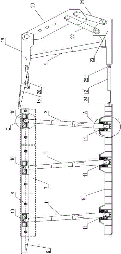
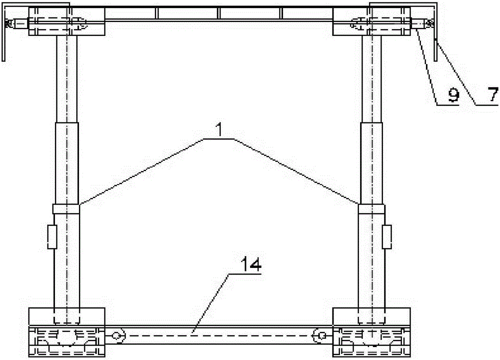
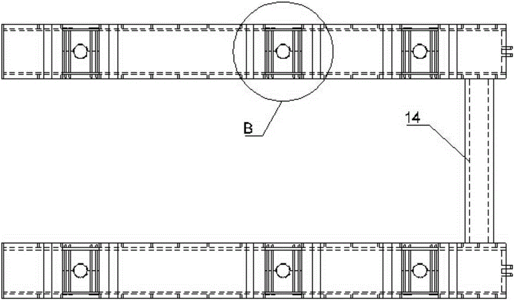
[0042] This embodiment provides a self-moving terminal hydraulic support based on a parallel mechanism, such as figure 1 As shown, it includes a front hydraulic support and a rear hydraulic support; wherein, the front hydraulic support includes two front bases 5, base connecting rods 14, front top beams 6 and front columns arranged in parallel, one of the two front bases 5 The side is fixedly connected by the base connecting rod 14. In this embodiment, the two ends of the base connecting rod 14 are fixedly connected to the two front bases 5 by means of bolt connection, and the two front bases 5 are symmetrically arranged with three rows of Front pillars (including the first row of front pillars 1, the second row of front pillars 2 and the third row of front pillars 3), the two ends of the front pillars are respectively hinged with the front top beam 6 and the front base 5, and the front top beam 6 is connected with the front The base 5 corresponds up and down; the rear hydraul...

Embodiment 2

[0051] This embodiment provides a self-moving terminal hydraulic support based on a parallel mechanism. The structure is as described in Embodiment 1, the difference is that the number of side guards 7 is three, and the three side guards 7 are arranged side by side. On the outer side of the front top beam 6 , each side guard 7 is hinged with two side push jacks 9 , and the side guard 7 is pushed out or pulled back by the two side push jacks 9 .

[0052] The application of the side pusher jack and the side guard can be adapted to the support of the ends of different widths, and the side guard is pushed out by the side pusher jack to contact the mine shaft wall. In addition, during the whole process of the hydraulic support at the end, the side guard can also adjust the walking position of the support. If the position of the front hydraulic support is shifted, the side guard can be pushed out by the side push jack to adjust the position of the front hydraulic support so that the...

Embodiment 3

[0054] This embodiment provides a self-moving terminal hydraulic support based on a parallel mechanism. The structure is as described in Embodiment 2. The difference is that a damping device is provided at the connection between the front column and the column socket, and the damping device is elastic. The limit damping device adopts rubber stopper in the present embodiment, and the damping device can limit the excessive inclination of the front column.


PUM


Abstract

The invention relates to a self-moving type termination point hydraulic support based on a parallel mechanism and application of the termination point hydraulic support. The self-moving type termination point hydraulic support comprises a front hydraulic support body and a rear hydraulic support body, wherein the front hydraulic support body and the rear hydraulic support body are connected through a pushing jack, the front hydraulic support body comprises two parallel front bases, a base connecting rod, a front top beam and front standing columns, one sides of the two front bases are fixedly connected through the base connecting rod, the plurality of front standing columns are symmetrically disposed on the two front bases, and two ends of the front standing columns are respectively hinged to the front top beam and the front bases. The self-moving type termination point hydraulic support has the advantages that the front hydraulic support body adopts the parallel mechanism, the front top beam is allowed to have six freedom degrees and can reach any spatial positions, the front top beam can be well combined with a top plate, top plate completeness is maintained greatly, the support is large in support force and support face, good in support effect and capable of achieving integral self-moving through hydraulic drive, manual carrying is not needed, working strength is lowered greatly, and work efficiency is increased evidently.

Description

technical field [0001] The invention relates to a self-moving terminal hydraulic support based on a parallel mechanism and its application, belonging to the technical field of mine equipment. Background technique [0002] The intersection of the roadway and the cut hole on the coal mining face of the coal mine is called the end, and the support used for the end is called the end support. The end part is the intersection point of equipment such as scraper conveyor and transfer machine, and it is also the throat part of pedestrian passage, ventilation, material transportation and coal transportation. The quality of the end support is the key to determine whether the working face can operate normally. According to the statistics of relevant safety departments, personal casualties at the end account for more than 60% of underground accidents, which must be paid attention to. [0003] At present, the end of the coal mining face is still mostly supported by a single hydraulic pr...

Claims


Application Information

Patent Timeline
Patent Type & Authority Applications(China)
IPC IPC(8): E21D23/04
CPCE21D23/04
Inventor 张鑫张文龙曾庆良万丽荣于鹏飞朱岩朋关旭东
Owner SHANDONG UNIV OF SCI & TECH
Learn More