Engine cylinder hole with composite micro-structure on surface

An engine cylinder and micro-topography technology, applied to engine components, machines/engines, cylinders, etc., can solve the problems of reduced surface support rate, poor emission performance, low processing efficiency, etc., to achieve increased surface support rate and reduced engine oil consumption , The effect of reducing fuel consumption

Inactive Publication Date: 2016-01-06
JIANGSU UNIV
View PDF6 Cites 6 Cited by
  • Summary
  • Abstract
  • Description
  • Claims
  • Application Information

AI Technical Summary

Problems solved by technology

[0006] The purpose of the present invention is to solve the deficiencies in the prior art, and provide an engine cylinder bore with composite microtopography on the su

Method used


Image

  • Engine cylinder hole with composite micro-structure on surface
  • Engine cylinder hole with composite micro-structure on surface
  • Engine cylinder hole with composite micro-structure on surface

Examples


Embodiment 1

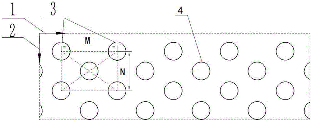
[0039] Such as figure 1 Shown is an embodiment of the engine cylinder bore with composite microtopography on the surface of the present invention, the cylinder bore is located on the engine block, the surface of the cylinder bore has a composite microtopography array, and the composite microtopography The appearance includes cavity A3 and cavity B4.

[0040] The concave cavity A3 is in a rectangular array, and the rectangular array is a rectangular array formed by the lines connecting the centers of gravity of four adjacent concave cavities A3; there is one concave cavity B4 inside the rectangle, and the concave cavity B4 has a The center of gravity coincides with the center of the rectangle.

[0041] Define the spacing of the cavity in the circumferential direction 1 of the cylinder bore as the circumferential spacing M, and the spacing of the cavity in the axial direction 2 of the cylinder bore as the axial spacing N.

[0042] The distribution density of the composite micr...

Embodiment 2

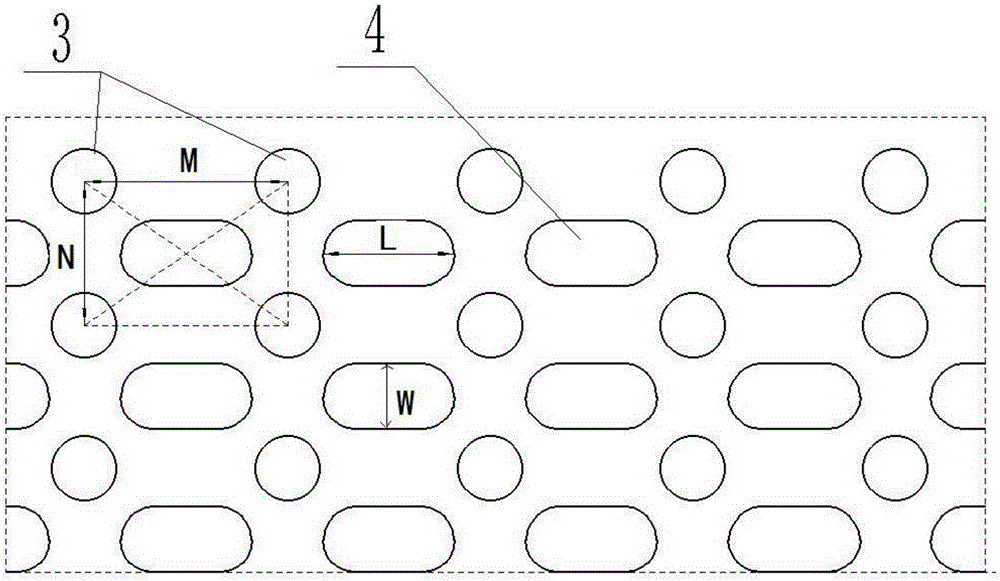
[0045] Such as figure 2 As shown, the difference between the second embodiment and the first embodiment is that the profile of the cavity B4 is a short groove, the length L∈[50,1000] μm of the cavity B, and the width W of the cavity B is the same as the The diameters of the cavities A3 are equal.

Embodiment 3

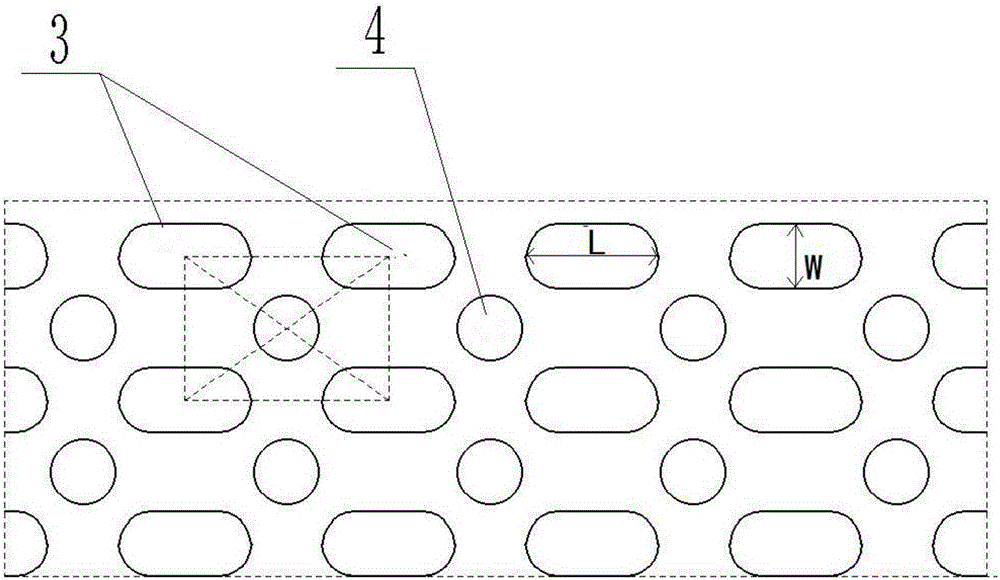
[0047] Such as image 3 As shown, the difference between the third embodiment and the first embodiment is that the profile of the cavity A3 is a short groove, and the profile of the cavity B4 is circular; the width W of the cavity A is the same as that of the cavity B4 The diameters are equal, the length L∈[50,300]μm of the cavity A, the depth ∈[2,10]μm of the cavity A3; the diameter ∈[10,100]μm of the cavity B4, the cavity B4 Depth ∈ [6,20] μm.


PUM


Abstract

The invention provides an engine cylinder hole with a composite micro-structure on the surface. A composite micro-structure array is arranged on the surface of the cylinder hole and comprises concave cavities A and concave cavities B; a rectangle is formed by the connecting lines of the gravity centers of every four adjacent concave cavities A; one concave cavity B is formed in each rectangle, and the gravity center of each concave cavity B coincides with the center of the corresponding rectangle; the structure contours of the concave cavities A and the concave cavities B are circles or short grooves; the concave cavities have a lubricating effect, the short grooves store lubricating oil, and the micro-structure distribution is made more even through the concave cavities and the short grooves; moreover, a uniform and continuous lubricating oil film and the dynamic pressure lubricating effect are formed in the working process of a cylinder hole-piston ring friction pair. By means of the engine cylinder hole, the tribological property of the cylinder hole-piston ring friction pair is obviously improved, and the abrasion resistance of the surface of the cylinder hole is improved; as for a whole engine, the fuel oil consumption is lowered by about 4%-5%, and the engine oil consumption is lowered by about 30%-50%.

Description

technical field [0001] The invention belongs to the field of internal combustion engines, in particular to an engine cylinder hole with composite microtopography on the surface. Background technique [0002] The cylinder bore-piston ring friction pair is one of the typical friction pairs in the engine, which determines the service performance and life of the engine, and the texture structure of the cylinder bore surface is closely related to the engine emission performance. In the past, the mechanical honing process was generally used in the machining of engine cylinder bores. By reducing the roughness of cylinder bores and forming cross-platform textures, the lubrication conditions between cylinder bores and piston ring friction pairs were improved. In recent years, with the advancement of special processing, especially high-energy laser processing technology, cylinder bore laser texturing technology has emerged. It has the advantages of energy saving and emission reductio...

Claims


Application Information

Patent Timeline
IPC IPC(8): F02F1/20
CPCF02F1/20
Inventor 康正阳符永宏华希俊纪敬虎王浩王林森
Owner JIANGSU UNIV
Why Eureka
Try Eureka