
A gas-liquid separation device

A gas-liquid separation device and gas outlet pipe technology, applied in refrigeration and liquefaction, refrigeration components, refrigerators, etc., can solve the problems of increasing material cost and processing cost, increasing condenser volume, etc. Thermal efficiency, the effect of increasing the heat exchange area

Active Publication Date: 2018-08-17
青岛同泰制冷科技有限公司
View PDF7 Cites 0 Cited by
  • Summary
  • Abstract
  • Description
  • Claims
  • Application Information

AI Technical Summary

Problems solved by technology

[0003] At present, the air conditioning unit realizes the supercooling of the refrigerant by adding a subcooling section in the condenser. This method will not only increase the volume of the condenser, but also increase the material cost and processing cost, which cannot meet the existing actual needs. Therefore, an improvement is urgently needed.

Method used


Image

  • A gas-liquid separation device

Examples


Embodiment Construction

[0013] The technical solutions of the present invention will be further described below in conjunction with the accompanying drawings and through specific implementation methods.

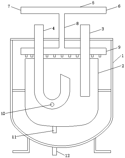
[0014] Such as figure 1 As shown, the gas-liquid separation device of the present invention includes: a first housing 1 and a second housing 2, the second housing 2 is located in the first housing 1, and on the second housing 2 An air inlet pipe 3 and an air outlet pipe 4 are provided, and the air inlet pipe 3 and the air outlet pipe 4 extend from the outside of the first housing 1 to the inside of the second housing 2, and the outside of the first housing 1 is provided The liquid inlet pipe 5, the liquid inlet pipe 5 has two nozzles, which are respectively the first nozzle 6 and the second nozzle 7, and a transition pipe 8 is communicated with the middle part of the liquid inlet pipe 5, and the transition pipe 8 is formed by the The outside of the first casing 1 extends to its interior, and the en...


PUM


Abstract

The invention discloses a gas-liquid separation device, which comprises a first shell and a second shell, the second shell is located in the first shell, an air inlet pipe and an air outlet pipe are arranged on the second shell, and the air inlet pipe and the air outlet pipe are formed by the first shell. The outside of the first casing extends to the inside of the second casing, and a liquid inlet pipe is arranged outside the first casing. The liquid inlet pipe has two nozzles, namely the first nozzle and the second nozzle, which are connected in the middle of the liquid inlet pipe. There is a transition pipe, and the transition pipe extends from the outside of the first shell to its inside, and the end of the transition pipe in the first shell is connected with a spray pipe, and a plurality of spray ports are arranged on the spray pipe, and the spray pipe Horizontally arranged above the second housing, the end of the outlet pipe located in the second housing is in a U-shaped structure, with a liquid return port at the bottom, and a liquid replenishment port at the bottom of the second housing, at the liquid replenishment port A solenoid valve for opening and closing the liquid replenishment port is provided, and a liquid discharge pipe is provided at the bottom of the first housing. The separation device of the present invention can realize the supercooling of the refrigerant without increasing the cost and improves the performance of the air conditioner.

Description

technical field [0001] The invention relates to the technical field of air conditioning, in particular to a gas-liquid separation device. Background technique [0002] The principle of air conditioning is that the refrigerant is compressed into a high-temperature and high-pressure gas through the compressor, and enters the condenser through the four-way valve. After the condenser absorbs cold and releases heat, it becomes a medium-temperature and high-pressure liquid. After passing through the expansion valve, it becomes a low-temperature and low-pressure liquid. After the evaporator absorbs heat and releases cold, it becomes a low-temperature and low-pressure gas, returns to the compressor through the four-way valve, and then continues the cycle. [0003] At present, the air conditioning unit realizes the supercooling of the refrigerant by adding a supercooling section in the condenser. This method will not only increase the volume of the condenser, but also increase the co...

Claims


Application Information

Patent Timeline
Patent Type & Authority Patents(China)
IPC IPC(8): F25B43/00F25B41/20
Inventor 羊绍元
Owner 青岛同泰制冷科技有限公司
Learn More