Automatic chip removal device for machine tool

An automatic discharge and machine tool technology, applied in metal processing machinery parts, maintenance and safety accessories, metal processing equipment, etc., can solve the problems of inconvenient collection of small debris, difficult to collect small debris, and inability to separate clean debris. , to achieve the effect of easy unified processing, novel structure design and resource saving

Active Publication Date: 2021-03-09
XINXIANG VOCATIONAL & TECHN COLLEGE
View PDF12 Cites 7 Cited by
  • Summary
  • Abstract
  • Description
  • Claims
  • Application Information

AI Technical Summary

Problems solved by technology

However, this method of using a rotating device to separate the iron filings from the coolant is not effective, and the chips in the coolant cannot be separated cleanly, and the compression of the rotating device by the compression mechanism cannot be realized, and it is easy to compress the rotating device. Bad, it is inconvenient to take materials, increase the input of equipment, and it is inconvenient to collect the small debris after separation
[0003] The existing chip removal device has a simple structure. The chips are conveyed out through the conveyor belt, and the small particle chips and the large chips are uniformly processed. Since the chips contain large pieces of chips, they occupy a lot of space, and there is a lot of space in the collection tank. It can be filled up in one block, which leads to frequent cleaning of the collection tank, which is labor-intensive and time-consuming, and the debris cannot be classified. Small debris is not easy to be collected, resulting in small debris everywhere in the workshop. The coolant contains fine debris, and the small debris is discharged along with the coolant. The existing chip removal device cannot collect the small debris in the coolant, and the chip removal effect is not good, and it is prone to blockage. A problem proposes an automatic chip removal device for machine tools

Method used


Image

  • Automatic chip removal device for machine tool
  • Automatic chip removal device for machine tool
  • Automatic chip removal device for machine tool

Examples


Embodiment 1

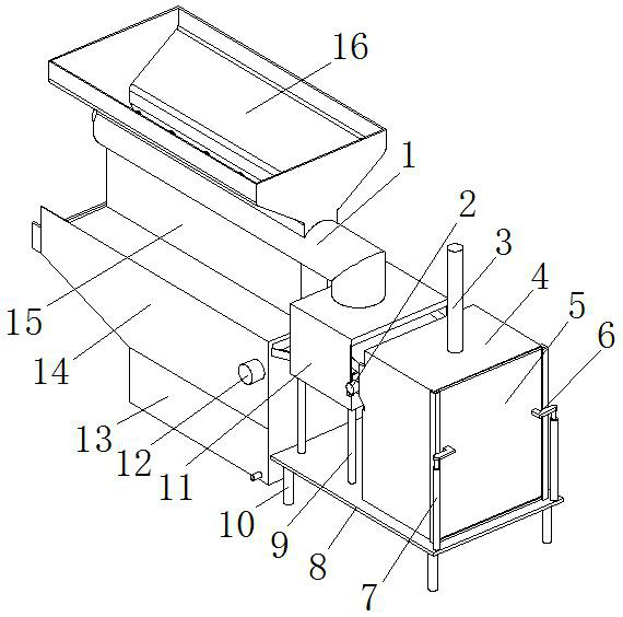
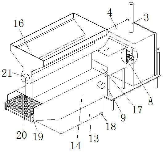
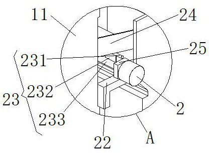
[0024] see Figure 1-6, the present invention provides a technical solution: an automatic chip removal device for machine tools, including a chip removal pipe 1, a chip compression box 4, a bottom plate 8, a slag-liquid separation box 11, a liquid storage box 13, a reciprocating swing mechanism 23 and a transmission frame 26. The inside of the chip discharge pipe 1 is provided with a screw discharge paddle 35, and the left end of the chip discharge pipe 1 is provided with a third motor 21. Connection, the chip discharge pipe 1 is provided with a debris collection tank 16, the discharge end of the chip discharge pipe 1 is connected with the slag-liquid separation box 11, the transmission frame 26 is set under the chip discharge pipe 1, and the transmission frame 26 is provided with a roller 28. A filter conveyor belt 19 is provided on the drum 28, a scraper 20 is provided at the left end of the transmission frame 26, one end of the scraper 20 is in contact with the surface of t...


PUM


Abstract

The invention discloses an automatic chip removal device for a machine tool. The device comprises a chip removal pipe, a chip compression box, a bottom plate, a slag-liquid separation box, a liquid storage box, a reciprocating swing mechanism and a conveying frame. A spiral discharging paddle is arranged in the chip removal pipe, a third motor is arranged at the left end of the chip removal pipe,and an output shaft of the third motor penetrates into the chip removal pipe and is connected with the spiral discharging paddle. A chip collecting groove is formed in the chip removal pipe, and the discharging end of the chip removal pipe is connected with the slag-liquid separation box. The conveying frame is arranged below the chip removal pipe, a roller is arranged on the conveying frame, a filtering conveying belt is arranged on the roller, cooling liquid and small-particle chips are separated through the filtering conveying belt, and the small-particle chips are conveyed out. A scrapingplate is arranged at the left end of the conveying frame. The automatic chip removal device for the machine tool is novel in structural design and good in chip removal effect, chip particles can be classified, separated treatment is facilitated, large chips are compressed, space is saved, frequent chip treatment is avoided, and time is saved.

Description

technical field [0001] The invention relates to the technical field of machine tool chip removal, in particular to an automatic chip removal device for machine tools. Background technique [0002] A machine tool refers to a machine that manufactures a machine, also known as a machine tool or a machine tool. It is customarily referred to as a machine tool. Machine tools play an important role in modern machinery manufacturing. In the process of machine tools processing mechanical workpieces, cutting tools will produce a large amount of chips, and the sizes of chips are different, and generate high temperature. The common method is to cool down through coolant, and these chips will be cooled The liquid rushes into the collection tank, and the debris in the collection tank needs to be removed by workers, and it is difficult to clean up. In the patent application number "201911041857.7", the patent name is "a kind of iron chip compaction device for machining centers", which dis...

Claims


Application Information

Patent Timeline
Patent Type & Authority Applications(China)
IPC IPC(8): B23Q11/00B23Q11/10
CPCB23Q11/0042B23Q11/1069
Inventor 韩昆朋杜金凤吕文龙
Owner XINXIANG VOCATIONAL & TECHN COLLEGE
Why Eureka
Try Eureka