Splicing device with single-spindle yarn suction nozzle structure and splicing method of splicing device

A yarn feeder and single-spindle technology, applied in the field of textile splicing equipment, can solve the problems of unsmooth running of the trolley, increased resistance of the trolley, and easy occurrence of yarn blocking, etc., and achieves the effect of simplifying the structure of the splicing trolley, simplifying the structure and increasing the resistance

Pending Publication Date: 2020-12-25
ANHUI RIFA TEXTILE MACHINERY
View PDF8 Cites 0 Cited by
  • Summary
  • Abstract
  • Description
  • Claims
  • Application Information

AI Technical Summary

Problems solved by technology

At present, each splicing trolley is equipped with a small suction nozzle. In order to provide negative pressure, the splicing trolley needs to open the air duct while moving, which makes the yarn suction channel long and complex in structure, which is prone to yarn blocking and winding problems. ; At the same time, it also adds a certain resistance to the walking of the trolley, causing the trolley to run unsmoothly
[0003] Existing splicing trolleys have complex structures and relatively large car bodies, such as figure 1 As shown, after receiving the splicing signal, the splicing trolley 1 moves along the track to the spindle position that needs splicing. The pipe 12 will be connected with the suction port 32 to provide negative pressure for the small suction nozzle 11, and the arrow indicates the direction of air flow
Splicing trolley 1 needs to open the damper every time it passes a spindle position, which increases the resistance of the trolley running and also has the risk of being stuck; in addition, it needs to provide a separate air duct and fan to form a negative pressure , so that the distance between the small suction nozzle 11 and the negative pressure tube 12 is longer, and the phenomenon of yarn winding and yarn blocking is easy to occur

Method used


Image

  • Splicing device with single-spindle yarn suction nozzle structure and splicing method of splicing device
  • Splicing device with single-spindle yarn suction nozzle structure and splicing method of splicing device
  • Splicing device with single-spindle yarn suction nozzle structure and splicing method of splicing device

Examples


Embodiment 1

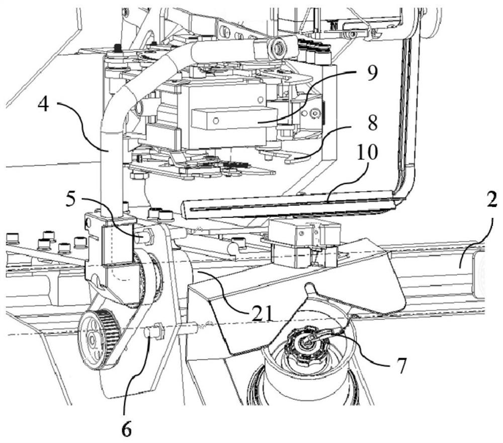
[0037] A splicing device with a single-spindle yarn suction nozzle structure in this embodiment, such as Figure 2~3 As shown, the single-spindle yarn suction nozzle 4 is included, and the single-spindle yarn suction nozzle 4 is fixedly installed on the wallboard of each spindle through the mounting seat 45 thereon; the single-spindle yarn suction nozzle 4 is connected with the upper The air door negative pressure air duct 21 is connected, and the negative pressure of the upper air door negative pressure air duct 21 is provided by the upper air duct 2, so that the distance between the single spindle yarn suction nozzle 4 and the upper air door negative pressure air duct 21 is relatively short, so there is no It is easy to cause yarn blocking phenomenon.

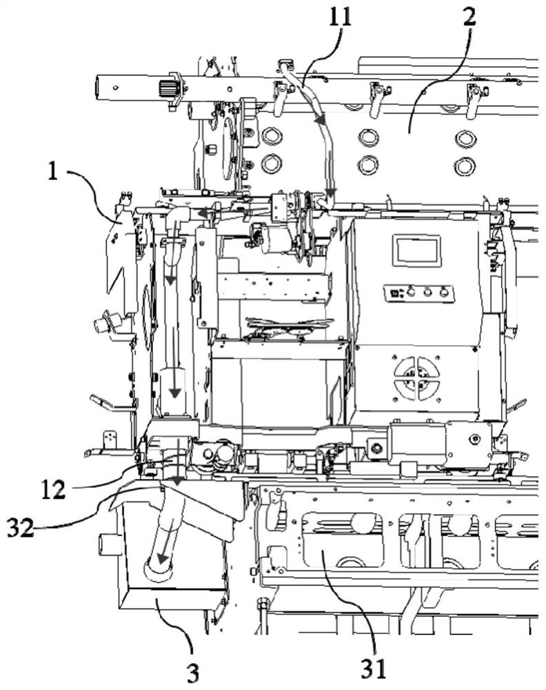
[0038]figure 1 It is a schematic diagram of the working state structure of the existing splicing trolley. After receiving the splicing signal, the splicing trolley 1 moves along the track to the spindle position that needs sp...

Embodiment 2

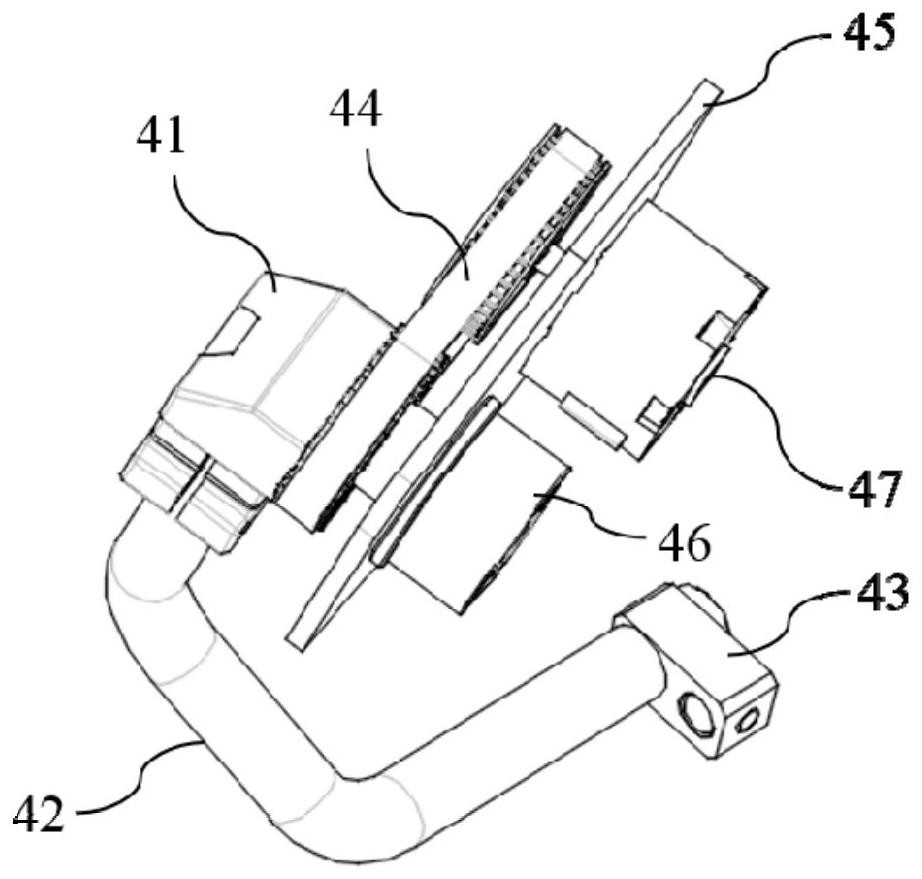
[0040] A splicing device with a single-spindle yarn suction nozzle structure in this embodiment, the basic structure is the same as that of embodiment 1, the differences and improvements are as follows: Figure 4 As shown, the single-spindle yarn suction nozzle 4 includes a suction nozzle elbow 41, a synchronous wheel 442 is installed inside the suction nozzle elbow 41, and a synchronous wheel shaft 443 is coaxially sleeved in the middle of the synchronous wheel 442. The wheel shaft 443 is also coaxially sleeved with a bearing 445, and each component is aligned with the axis of the connecting pipe 46 and is detachably installed on the mounting seat 45; the same side of the mounting seat 45 as the synchronous wheel 442 is also equipped with a driving wheel 441, the middle part of the drive wheel 441 is coaxially connected with a swing cylinder 47, thereby providing a drive source; the drive wheel 441 and the synchronous wheel 442 are sleeved with a synchronous belt 444 to realiz...

Embodiment 3

[0043] A splicing device with a single-spindle yarn suction nozzle structure in this embodiment, the basic structure is the same as that of embodiment 2, the differences and improvements are as follows: figure 2 As shown, the upper and lower zero sensors 5 and 6 are horizontally installed on the mounting base 45 respectively. Driven by a motor, the positioning of the sensors is required, so that the positioning of the swing cylinder 47 is accurate and the adjustment is simple.

[0044] In this example, if Figure 2~4 As shown, by starting the swing cylinder 47, the driving wheel 441 is driven to rotate forward or reversely, and then the synchronous wheel 442 is driven to rotate in the same direction through the synchronous belt 444 wound on it, so as to control the suction nozzle elbow 41 installed thereon. Rotate, and then drive the yarn suction nozzle 42 connected to the bottom of the suction nozzle elbow 41 to go down or up, and correspondingly drive the suction nozzle mou...


PUM


Abstract

The invention discloses a splicing device with a single-spindle yarn suction nozzle structure and a splicing method of the splicing device, and belongs to the technical field of textile splicing equipment. According to the splicing device with the single-spindle yarn suction nozzle structure and the splicing method of the splicing device, the splicing device comprises a single-spindle yarn suctionnozzle, wherein the single-spindle yarn suction nozzle is fixedly mounted on a wallboard of each spindle through a mounting base on the single-spindle yarn suction nozzle; the single-spindle yarn suction nozzle communicates with the upper air door negative-pressure air pipe through a connecting pipe, so that the distance between the single-spindle yarn suction nozzle and the upper air door negative-pressure air pipe is relatively short, and the phenomena of yarn winding and yarn blocking are not prone to occurring; and the single-spindle yarn suction nozzle comprises a suction nozzle elbow, the lower part of the suction nozzle elbow is connected with a yarn suction nozzle body, the yarn suction nozzle body is fixed to the suction nozzle elbow in a hooping mode and is matched with a sensorfor positioning, and therefore, a swing air cylinder is accurate in positioning and easy to adjust and the yarn suction nozzle body can rotate around the suction nozzle elbow and swing up and down.

Description

technical field [0001] The invention relates to the technical field of textile splicing equipment, in particular to a splicing device with a single-spindle yarn suction nozzle structure and a splicing method thereof. Background technique [0002] The structure of the vortex spinning device is simple, and the high-speed rotating parts are canceled, and the moving yarn is twisted by means of the high-speed rotating airflow. During vortex spinning, the fibers are twisted by means of an air flow. At present, each splicing trolley is equipped with a small suction nozzle. In order to provide negative pressure, the splicing trolley needs to open the air duct while moving, which makes the yarn suction channel long and complex in structure, which is prone to yarn blocking and winding problems. ; At the same time, it also adds a certain resistance to the walking of the trolley, which causes the trolley to run unsmoothly. [0003] Existing splicing trolleys have complex structures an...

Claims


Application Information

Patent Timeline
Patent Type & Authority Applications(China)
IPC IPC(8): B65H69/06
CPCB65H69/061B65H2553/80
Inventor 张越锋陈国樑
Owner ANHUI RIFA TEXTILE MACHINERY
Why Eureka
Try Eureka