Solar power station having battery panels capable of performing multi-degree-freedom movement

A degree of freedom and battery panel technology, applied in the field of solar power stations, can solve the problems of low solar energy utilization rate and poor flexibility of solar panels, and achieve the effect of flexible and free tilting range, compact structure and small footprint

Inactive Publication Date: 2016-01-06
HEILONGJIANG XINGAN NEW ENERGY
View PDF7 Cites 5 Cited by
  • Summary
  • Abstract
  • Description
  • Claims
  • Application Information

AI Technical Summary

Problems solved by technology

[0003] The purpose of the present invention is to provide a solar power station with multi-degree-of-freedom movement of battery panels to solve the problems of poor flexibility of solar panels and low utilization rate of solar energy when using existing solar power vehicles

Method used


Image

  • Solar power station having battery panels capable of performing multi-degree-freedom movement
  • Solar power station having battery panels capable of performing multi-degree-freedom movement
  • Solar power station having battery panels capable of performing multi-degree-freedom movement

Examples


specific Embodiment approach 1

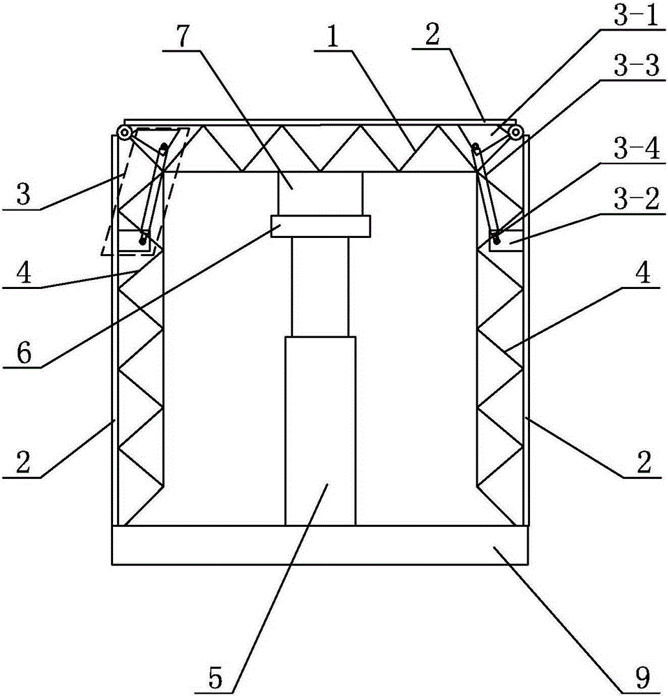
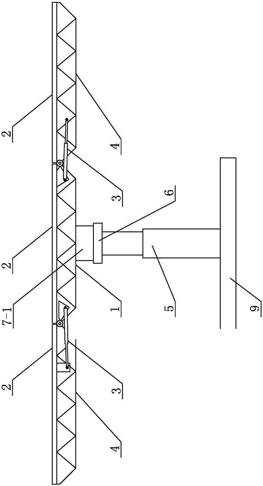
[0022] Specific implementation mode one: combine figure 1 , figure 2 , image 3 , Figure 4 , Figure 5 , Figure 6 , Figure 7 and Figure 8 Describe this embodiment, which includes a general base 9, a lifting mechanism 5, a slewing mechanism 6, a tilting mechanism 7, an upper truss 1, a plurality of side trusses 4, a plurality of actuators 3 and a plurality of solar panels 2, The general base 9 is arranged horizontally, the lifting mechanism 5, the slewing mechanism 6, the tilting mechanism 7, and the upper truss 1 are sequentially arranged on the general base 9 from bottom to top, and the plurality of side trusses 4 are evenly arranged on the upper truss 1 around, each side truss 4 is hinged with the upper truss 1, a solar cell panel 2 is arranged on the top surface of each side truss 4 and the top surface of the upper truss 1, and the solar cell panel 2 on each side truss 4 It is connected with the solar panel 2 on the top surface of the upper truss 1 through an ac...

specific Embodiment approach 2

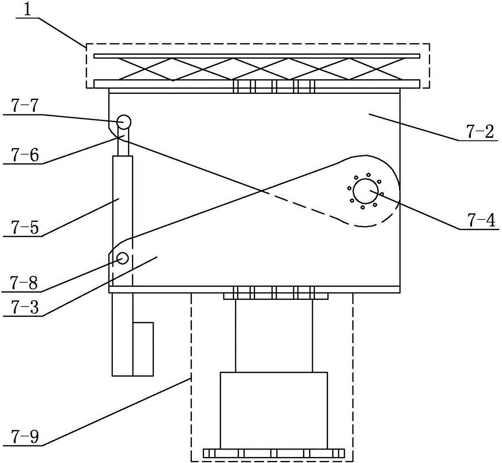
[0024] Specific implementation mode two: combination figure 1 , figure 2 , image 3 and Figure 4 Describe this embodiment, the tilting mechanism 7 of this embodiment includes a housing 7-1, a moving seat body 7-2, a static seat body 7-3, a tilting shaft 7-4, an electric push rod cover 7-5 and an electric push and pull rod 7-6 , the moving shaft 7-7 and the static shaft 7-8, the moving seat body 7-2, the static seat body 7-3 and the tilting shaft 7-4 are all located in the shell 7-1, the moving seat body 7-2 and the The bottom surface of the upper truss 1 is fixedly connected, the static seat body 7-3 is fixedly connected to the slewing mechanism 6, the static seat body 7-3 is hinged with the dynamic seat body 7-2 through the tilting shaft 7-4, and the electric pusher The rod sleeve 7-5 is hinged with the static seat body 7-3 through the static shaft 7-8, and one end of the electric push-pull rod 7-6 is inserted in the electric push rod sleeve 7-5, and the electric push-pu...

specific Embodiment approach 3

[0027] Specific implementation mode three: combination figure 1 , figure 2 , Figure 5 and Figure 6 Describe this embodiment, the lifting mechanism 5 described in this embodiment includes a lower flange 5-1, an upper flange 5-2, a lower oil cylinder seat 5-3, an upper oil cylinder seat 5-4, an oil cylinder 5-5, a fixed slide Block 5-6, movable slider 5-7, outer support body 5-8 and inner support body 5-9, the inner wall of described outer support body 5-8 is provided with fixed slider 5-6, inner support body 5 -9 is provided with a movable slider 5-7 on the outer wall, the inner support body 5-9 is sleeved in the outer support body 5-8 and is slidably connected with the outer support body 5-8, the outer support body 5-8 The bottom is fixedly connected to the lower flange 5-1, the top of the inner support body 5-9 is fixedly connected to the upper flange 5-2, the oil cylinder 5-5 is located in the inner support body 5-9, and the oil cylinder The cylinder barrel in 5-5 is ...


PUM


Abstract

The invention relates to a solar power station having battery panels capable of performing multi-degree-freedom movement, relating to the solar generating case. The invention solves the problems that the solar battery panels of the current solar generating vehicle are poor in flexibility and solar energy utilization rate is low. The solar power station having battery panels capable of performing multi-degree-freedom movement comprises a master base, a lifting mechanism, a revolution mechanism, a tilting mechanism, an upper truss, a plurality of side trusses, a plurality of execution mechanisms and a plurality of solar battery panels. The lifting mechanism, the revolution mechanism, the tilting mechanism, and the upper truss are arranged on the master base; the plurality of side trusses are arranged on the circumference of the upper truss; each side truss is hinged with the upper truss; the top surface of each side truss and the top surface of the upper truss are provided with solar battery panels; and the solar battery panel of each side truss is connected to the solar battery panel on the top surface of the upper truss through the execution mechanism. The invention is easy to use and the effective area for absorbing the solar energy is big. Meanwhile, the invention also has functions of tilting, revolution and lifting, and improves the flexibility. The invention is used for solar power generating.

Description

technical field [0001] The invention relates to a solar power station in which battery panels can move with multiple degrees of freedom. Background technique [0002] A solar power station is a device that uses solar cell components to convert light energy into electrical energy. It is a clean and renewable energy source for the earth. in solar photovoltaic power generation systems. Since the power generated by solar photovoltaics is directly proportional to the photovoltaic cell components, solar power generation has been limited and poor in flexibility due to the fact that solar power generation has always stayed in a fixed area, resulting in a solar power generation car. Although the solar power generation car breaks the traditional fixed position for solar energy The power generation mode is mobile power generation, but due to the effective vehicle body area, the area of ​​the solar power generation panel is also limited, so that the solar energy absorbed by the solar p...

Claims


Application Information

Patent Timeline
Patent Type & Authority Applications(China)
IPC IPC(8): H02S20/32H02S10/40
CPCY02E10/50
Inventor 于丰泽陈怀春于占江
Owner HEILONGJIANG XINGAN NEW ENERGY
Why Eureka
Try Eureka