
Self-located telephone receiver

A receiver and self-positioning technology, which is applied in the direction of handset/earphone accessories, etc., can solve the problems affecting the performance of the receiver, scrapping, etc., and achieve the effect of high precision and accurate positioning

Active Publication Date: 2016-01-06
SUZHOU E AUDIO ELECTRONICS
View PDF4 Cites 4 Cited by
  • Summary
  • Abstract
  • Description
  • Claims
  • Application Information

AI Technical Summary

Problems solved by technology

The space between the upper end of the conductive rod and the vibrating membrane is small. During the assembly process, if the positioning is wrong, the performance of the receiver will be affected or even scrapped.

Method used


Image

  • Self-located telephone receiver
  • Self-located telephone receiver
  • Self-located telephone receiver

Examples


Embodiment

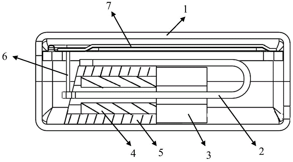
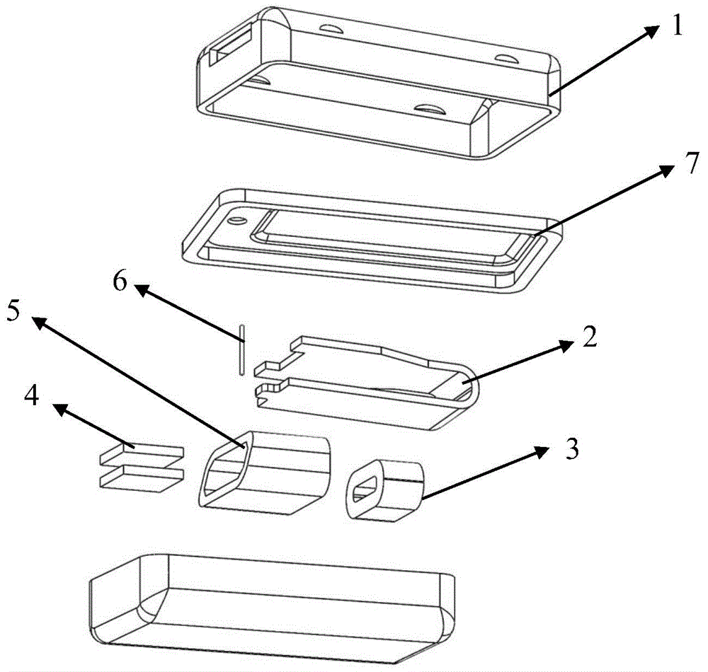
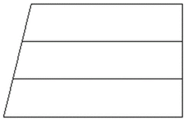
[0021] Such as figure 1 , figure 2 , image 3 As shown, a self-positioning receiver includes a housing 1, a reed 2, a coil 3, a magnet 4, a yoke 5, and a vibrating membrane 7. The vibrating membrane 7 is arranged in an upper cover, and the outer housing 1 includes a bottom box and an upper cover. The reed 2 includes a fixed part and a vibrating part. The coil 3 and the yoke 5 are sheathed on the vibrating part in turn. The upper and lower sides of the vibrating part are respectively provided with magnets 4. The magnet 4 and the inner surface of the yoke 5 Fixed connection, the vibrating part is connected to the vibrating membrane 7 through the transmission rod 6, the yoke 5 is an enclosed structure, formed by four surfaces of the upper bottom, the lower bottom, the left side and the right side, and the yoke 5 is fixed in the shell, wherein The length of the upper bottom near the front end of the shell is shorter than the length of the lower bottom. The joints of the upper ...


PUM


Abstract

The invention discloses a self-located telephone receiver. The self-located telephone receiver comprises a shell, a reed, a coil, magnets and a magnet yoke; the shell comprises a bottom box and an upper cover; the reed comprises a fixed part and a vibration part; the coil and the magnet yoke sleeve the vibration part sequentially; the magnets are respectively arranged at the upper and lower sides of the vibration part; the magnets are fixedly connected with the inside surface of the magnetic yoke; the vibration part is in transmission connection with a vibration film through a conduction rod; the magnet yoke is an encircled structure and formed by an upper bottom, a lower bottom, a left side and a right side; and the magnet yoke is fixed in the shell, wherein the upper bottom surface near the front end of the shell is shorter than the lower bottom surface. A space for containing the reed and the conduction rod, combining the reed with the condition rod and enabling the reed and the conduction rod to freely vibrate is at the front end of the upper bottom surface and the bottom box; therefore, when the telephone receiver is assembled, the lower bottom surface of the magnet yoke is only necessary to resist the front end of the bottom box; an extra locating fixture is unnecessary; and the self-located telephone receiver is accurate to locate and high in precision.

Description

technical field [0001] The present invention relates to receiver structures. Background technique [0002] At present, most of the magnetic yoke structures used for receivers or transducers on the market are designed to be enclosed. When installing the magnetic yoke structure into the receiver box, a specific positioning fixture is required for measurement and positioning, and then the magnetic yoke structure is fixed on the Locate the established position, so as to ensure the combination and free vibration space of the reed of the receiver and the conducting rod. The space between the upper end of the conductive rod and the vibrating membrane is small. During the assembly process, if the positioning is wrong, the performance of the receiver will be affected or even scrapped. Contents of the invention [0003] In order to solve the deficiencies in the prior art, the present invention provides a receiver magnetic yoke structure with a self-positioning function. The assembl...

Claims


Application Information

Patent Timeline
IPC IPC(8): H04R1/10
Inventor 薛洪明张春刚刘洋
Owner SUZHOU E AUDIO ELECTRONICS
Learn More