Supercharge Your Innovation With Domain-Expert AI Agents!

Solar photovoltaic substrate gantry type centrifugal rotary brush cleaning device

A technology for photovoltaic substrates and cleaning devices, applied in cleaning methods and tools, cleaning methods using tools, chemical instruments and methods, etc., can solve problems such as accumulated gravel, scratches on photovoltaic panels, accumulation of gravel veneers, etc., to achieve protection and Long service life, high cleaning efficiency, and extended service life

Active Publication Date: 2017-09-22
SHANDONG UNIV +1
View PDF7 Cites 0 Cited by
  • Summary
  • Abstract
  • Description
  • Claims
  • Application Information

AI Technical Summary

Problems solved by technology

[0003] 1. The cleaning mechanism of the long-axis roller brush mostly adopts the structure of a long-axis spiral roller (tube) brush or a long-axis straight roller cloth brush installed directly in the housing cover (the rotating roller brush directly contacts the surface of the solar photovoltaic substrate), The main defect of this structure is that in the windy and sandy climate, it will cause the accumulation of sand and gravel in the outer casing and the veneer on the long-axis roller brush, especially the accumulated sand and dust on the spiral barrel brush and in the outer casing is not only difficult to remove, but also There is a hidden danger of falling and accumulating sand and gravel during the cleaning work, which may cause scratches on the partial surface of the photovoltaic panel;
[0004] 2. The mechanical structure and rotation speed of the long-axis roller brush limit the cleaning quality of this long-axis roller (tube) brush. It is difficult for a cleaning machine with a long-axis roller brush structure to clean the surface of solar photovoltaic substrates through one or two cleanings, so it needs multiple cleanings to achieve it; and frequent multiple cleanings will quickly shorten the solar photovoltaic surface. Substrate Lifetime

Method used


Image

  • Solar photovoltaic substrate gantry type centrifugal rotary brush cleaning device
  • Solar photovoltaic substrate gantry type centrifugal rotary brush cleaning device
  • Solar photovoltaic substrate gantry type centrifugal rotary brush cleaning device

Examples


Embodiment Construction

[0034] Below in conjunction with accompanying drawing and embodiment the present invention will be further described:

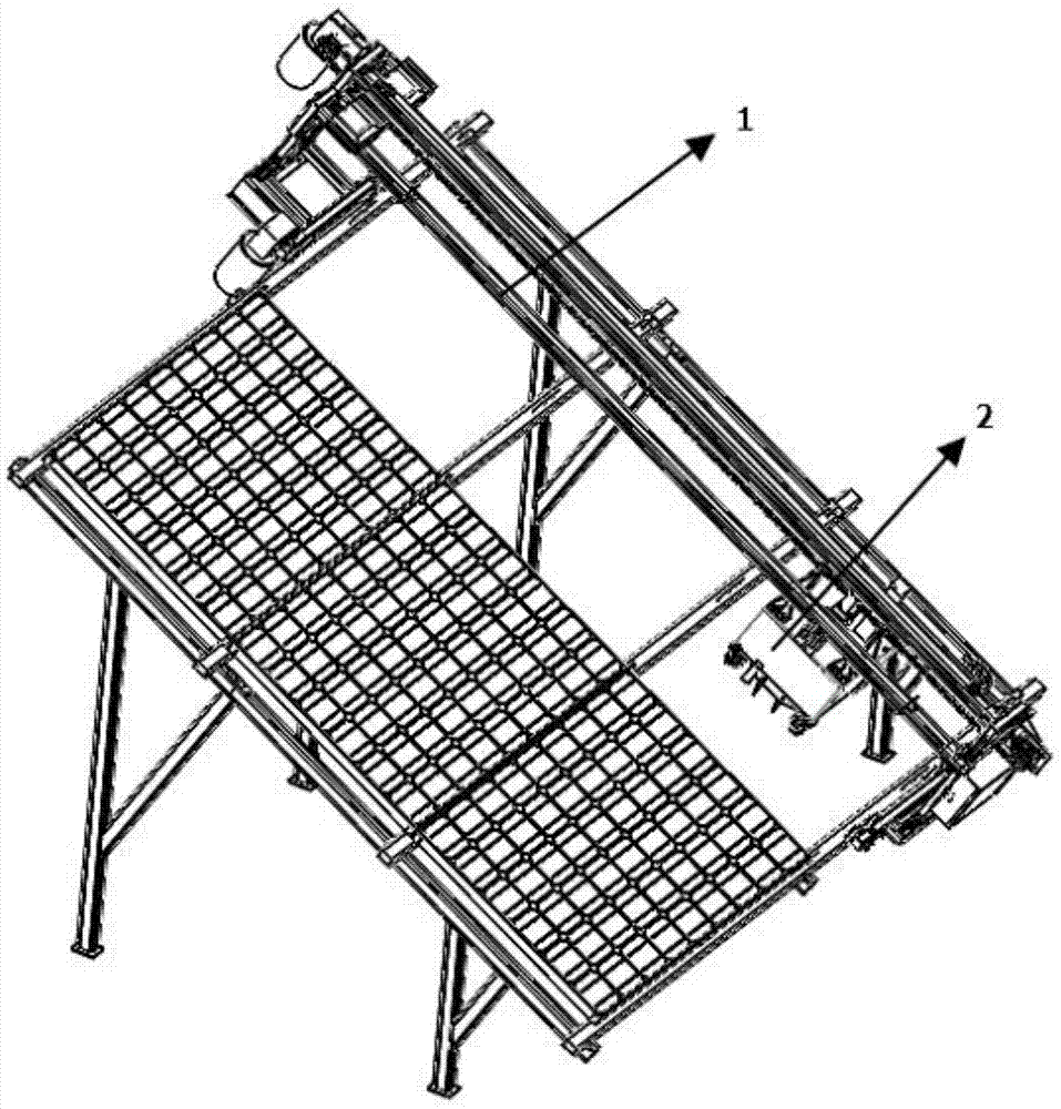
[0035] Such as figure 1 As shown, the solar photovoltaic substrate gantry type centrifugal cleaning device includes a gantry mechanical walking mechanism 1 and a centrifugal rotary cleaning mechanism 2. The centrifugal rotary cleaning mechanism 2 is hoisted on the gantry mechanical walking mechanism 1, and can The rail-type connecting profile 4 of the gantry-type mechanical traveling mechanism 1 moves left and right; The rotary brush cleaning mechanism 2 moves back and forth under the drive of the traversing active mechanism 3 and the traversing driven mechanism 5; the centrifugal rotary brush cleaning mechanism 2 cleans the objects to be cleaned while moving back and forth, left and right.

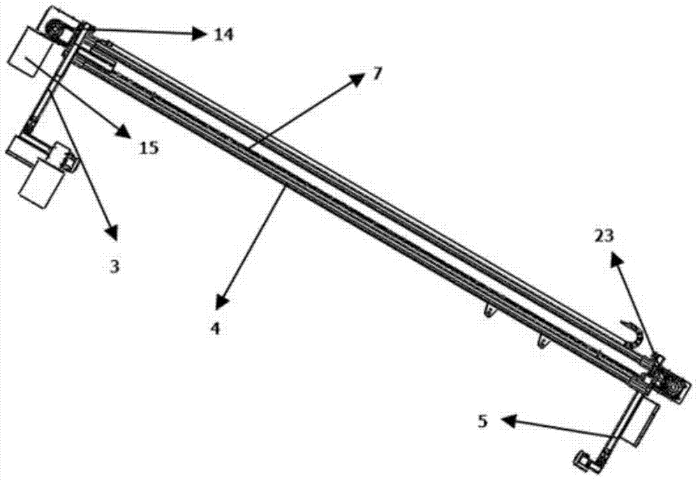
[0036] Such as figure 2 As shown, the gantry-type mechanical traveling mechanism 1 of the present invention mainly includes a rail-type connection profile 4 , a first...


PUM


Abstract

The invention discloses a gantry-type centrifugal whisk cleaning device for solar photovoltaic substrates, which includes a gantry-type mechanical traveling mechanism and a centrifugal whisk cleaning mechanism. The centrifugal-type whisk cleaning mechanism is hoisted on the gantry-type mechanical traveling mechanism and can move along the gantry-type mechanical traveling mechanism. The guide-rail connecting profile of the mechanical traveling mechanism moves left and right; the gantry-type mechanical traveling mechanism is installed on the traversing active mechanism and the traversing driven mechanism, and the gantry-type mechanical traveling mechanism and the centrifugal rotating whisk cleaning mechanism are installed on the traversing active mechanism and the traversing driven mechanism. Driven by the driven mechanism, it realizes forward and backward movement; the centrifugal whisk cleaning mechanism moves forward, backward, left and right while cleaning the object to be cleaned. It can efficiently clean solar photovoltaic substrates with good cleaning effect.

Description

technical field [0001] The invention relates to the technical field of cleaning solar photovoltaic substrates, in particular to a gantry-type centrifugal rotary brush cleaning device for solar photovoltaic substrates. Background technique [0002] The current solar photovoltaic substrate cleaning machines (cleaning robots) basically use the cleaning structure of the long-axis rotating roller brush. This cleaning structure of the long-axis roller brush has some technical defects: [0003] 1. The cleaning mechanism of the long-axis roller brush mostly adopts the structure of a long-axis spiral roller (tube) brush or a long-axis straight roller cloth brush installed directly in the housing cover (the rotating roller brush directly contacts the surface of the solar photovoltaic substrate), The main defect of this structure is that in the windy and sandy climate, it will cause the accumulation of sand and gravel in the outer casing and the veneer on the long-axis roller brush, es...

Claims


Application Information

Patent Timeline
Patent Type & Authority Patents(China)
IPC IPC(8): B08B1/04B08B13/00
CPCB08B13/00B08B1/32B08B1/12
Inventor 马庆潘宁吴皓
Owner SHANDONG UNIV
Features
  • R&D
  • Intellectual Property
  • Life Sciences
  • Materials
  • Tech Scout
  • Unparalleled Data Quality
  • Higher Quality Content
  • 60% Fewer Hallucinations
Learn More