Three-way loading and bending elbow pipe device and method

A technology of pipe bending device and axial loading, applied in the field of three-way loading bending pipe bending device, can solve the problems of reducing wall thickness, stretching the center of the elbow, exceeding the wall thickness, etc. Long and eliminate the effect of thinning and ultra-tolerance of the wall thickness of the elbow

Inactive Publication Date: 2016-01-13
SHANGHAI NUCLEAR ENG RES & DESIGN INST CO LTD
View PDF5 Cites 0 Cited by
  • Summary
  • Abstract
  • Description
  • Claims
  • Application Information

AI Technical Summary

Problems solved by technology

Therefore, during the bending deformation process of the elbow, the center of the elbow is elongated because the outer arc side of the elbow is elongated more than the inner arc side is not compressed.
At the same time, the outer arc side of the elbow is further reduced in wall thickness during the elongation process, which will cause the wall thickness to exceed the standard in severe cases

Method used


Image

  • Three-way loading and bending elbow pipe device and method
  • Three-way loading and bending elbow pipe device and method
  • Three-way loading and bending elbow pipe device and method

Examples


Embodiment 1

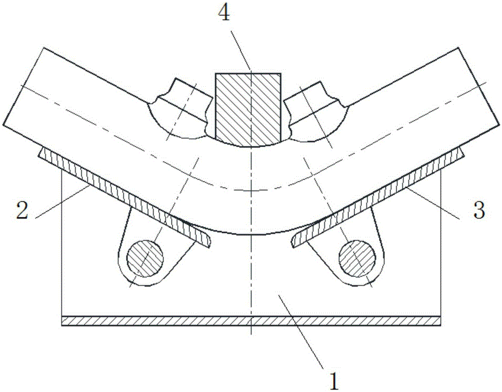
[0043] Such as Figure 4 As shown, the three-way loading bending device includes:

[0044] pedestal 1;

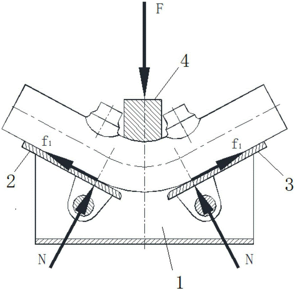
[0045] The left lower mold 2 and the right lower mold 3; the left lower mold 2 and the right lower mold 3 are arranged on the base frame 1, and are arranged on the same horizontal plane, and are used to support the pipe 01 to be bent; the left lower mold 2 and the Described right lower die 3 all can be rotated; After described left lower die and described right lower die rotate, be V-shaped setting (such as Figure 5 shown);

[0046] Upper mold 4; Said upper mold 4 is arranged on said pedestal 1, can rise or fall; Pipe 01 exerts downward pressure F to make the pipe to be bent bend (such as Figure 5 shown);

[0047] Axial loading device; the axial loading device is arranged on the base frame, and loads the pipe to be bent along the axial direction of the pipe to be bent.

[0048] Preferably, the axial loading device includes a loading pad 51; the loading pad 51 is arr...

Embodiment 2

[0068] Such as Figure 6 As shown, different from Embodiment 1, the screw nut 53 of this embodiment is located at the end of the screw rod 52 and abuts against the loading pad 51 . The screw nut 53 rotates to push the loading block 51 to apply pressure to the pipe to be bent along the axial direction of the pipe to be bent.

[0069] Except for the above-mentioned structure, the other structures of the three-way loading bending pipe bending device of this embodiment are the same as those of the device in Embodiment 1.

Embodiment 3

[0071] Such as Figure 7 As shown, different from Embodiment 1, the transmission device of this embodiment also includes a hydraulic device 54, which is connected to the loading pad 51; after the hydraulic device 54 is stretched, it drives the loading pad 51 applies pressure to the pipe to be bent 01 along the axial direction of the pipe to be bent.

[0072] Except for the above-mentioned structure, the other structures of the three-way loading bending pipe bending device of this embodiment are the same as those of the device in Embodiment 1.


PUM

PropertyMeasurementUnit
sizeaaaaaaaaaa

Abstract

The invention provides a three-way loading and bending elbow pipe device and method. The three-way loading and bending elbow pipe device and method are characterized in that the three-way loading bending and elbow pipe device comprises a base frame, a lower left mold, a lower right mold, an upper mold and an axial loading device; the lower left mold and the lower right mold are arranged on the base frame in the same horizontal plane and are used for supporting a pipe to be bent; the lower left mold and the lower right mold are both capable of rotating; after the lower left mold and the lower right mold rotate, the lower left mold and the lower right mold are arranged in a V type; the upper mold is arranged on the base frame and can be lifted or declined; after the upper mold is declined, downward pressure is exerted on the pipe to bent supported on the lower left mold and the lower right mold, and the pipe to be bent is bent; the axial loading device is arranged on the base frame and conducts loading on the pipe to be bent in the axial direction of the pipe to be bent. The three-way loading and bending elbow pipe device can offset the friction force of the molds when bending is conducted, compensate the difference between the tensile deformation force and the compression deformation force of the elbow pipe, and eliminate the phenomena that the centerline extension and the wall thickness reduction of the elbow pipe are out of tolerance.

Description

technical field [0001] The invention relates to a device for bending pipes with three-way loading and a method for bending pipes using the device. Background technique [0002] At present, the manufacture of large-diameter thick-walled pipe generally adopts machining forming, intermediate frequency bending, hot bending and cold bending. Among them, when mechanical cutting is used for forming, the shape of the elbow is good, the bending radius is uniform, the bending angle is precise, and there is no phenomenon of wall thickness reduction and centerline elongation of the elbow. However, special machining equipment is required, which is difficult to machine and takes a long time to process, especially the machining of austenitic stainless steel elbows is extremely difficult; when intermediate frequency elbows are used, the bending radius of the elbow is uniform and the forming speed of the elbow is fast. However, it is difficult to control the thinning of the wall thickness o...

Claims


Application Information

Patent Timeline
Patent Type & Authority Applications(China)
IPC IPC(8): B21D7/06
Inventor 施永兵张玉徐臻陈敏蒋运友钟林秀戴兴国
Owner SHANGHAI NUCLEAR ENG RES & DESIGN INST CO LTD
Why Eureka
Try Eureka