LNG (Liquefied Natural Gas) energy recovery process

A technology of energy recovery and process, applied in the direction of steam engine devices, machines/engines, mechanical equipment, etc., can solve the problems of increasing BOG processing costs, high-grade energy loss, and large BOG volume, so as to save power consumption, effectively recover, and BOG The effect of volume reduction

Active Publication Date: 2016-01-13
JEREH OIL & GAS ENG
View PDF8 Cites 86 Cited by
  • Summary
  • Abstract
  • Description
  • Claims
  • Application Information

AI Technical Summary

Problems solved by technology

[0003] The general manufacturing process of liquefied natural gas is to liquefy the purified natural gas into high-pressure and low-temperature LNG through various refrigeration processes, and then further throttling and reducing the pressure through the Joule-Thomson (J-T) valve to for

Method used


Image

  • LNG (Liquefied Natural Gas) energy recovery process

Examples


Example Embodiment

[0026] Example 1:

[0027] LNG hydraulic turbine device (or other forms of expansion machinery) Take LNG hydraulic turbine device as an example:

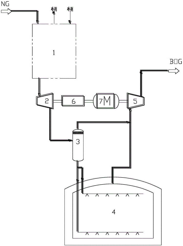
[0028] Such as figure 1 Shown is a schematic flow diagram of an LNG energy recovery process, including:

[0029] The natural gas purified by the pretreatment device enters the cold box 1, exchanges heat with the refrigerant in the heat exchanger in the cold box, and is liquefied through the pre-cooling and cryogenic process to form high-pressure and low-temperature LNG. The LNG is passed through the LNG hydraulic turbine unit. The expansion end 2 depressurizes, converts its own pressure energy into mechanical energy, and outputs low-temperature and low-pressure LNG; after the low-temperature and low-pressure LNG is separated into gas and liquid by the gas-liquid separation tank 3, the liquid phase LNG is sent to the LNG storage tank 4 for storage, and the gas phase The BOG merges with the BOG from the LNG storage tank 4, is pressurized b...

Example Embodiment

[0034] Example 2:

[0035] The expansion end 2 of the LNG hydraulic turbine device is of axial flow type.

[0036] A drive mode switching device 6 is provided between the expansion end 2 of the LNG hydraulic turbine device and the electric motor 7, and the drive mode switching device 6 adopts a hydraulic coupling.

[0037] The other parts are the same as in embodiment 1.

[0038] After a large number of tests, the process of the present invention can increase the LNG output by about 1% to 3% compared with the original LNG output (using Joule-Thomson (J-T) valve).

Example Embodiment

[0039] Example 3:

[0040] The expansion end 2 of the LNG hydraulic turbine device is of screw type.

[0041] A drive mode switching device 6 is provided between the expansion end 2 of the LNG hydraulic turbine device and the electric motor 7, and the drive mode switching device 6 adopts an overspeed clutch.

[0042] The other parts are the same as in embodiment 1.

[0043] After a large number of tests, the process of the present invention can increase the LNG output by about 1% to 3% compared with the original LNG output (using Joule-Thomson (J-T) valve).


PUM


Abstract

The invention relates to the technical field of natural gas low temperature equipment, in particular to an LNG energy recovery process. By an LNG hydraulic turbine device (or expanding machinery in other forms), high pressure and low temperature LNG converts pressure energy to mechanical energy which is output by a supercharging end of the LNG hydraulic turbine device. Depressurized LNG is further cooled, a gas phase and a liquid phase generated in a depressurizing process are separated by a gas-liquid separation tank, the liquid LNG is charged to an LNG storage tank, and the gas phase BOG and BOG of the LNG storage tank are supercharged together by the supercharging end, namely, a BOG supercharger, of the LNG hydraulic turbine device. The LNG hydraulic turbine device replaces a J-T valve of the LNG product for expanding throttling, as the LNG is lower in temperature, output of the BOG is reduced, LNG yield is improved, and mechanical energy can be recovered by BOG supercharging of the BOG supercharging end.

Description

technical field [0001] The invention relates to the technical field of natural gas cryogenic equipment, in particular to an LNG energy recovery process. Background technique [0002] Liquefied Natural Gas (LNG for short), whose main component is methane, is recognized as the cleanest energy on earth. Colorless, odorless, non-toxic and non-corrosive, its volume is about 1 / 625 of the volume of the same volume of gaseous natural gas, and the weight of liquefied natural gas is only about 45% of the same volume of water. The burning of liquefied natural gas causes very little air pollution and releases a lot of heat, so liquefied natural gas is a relatively advanced energy source. [0003] The general manufacturing process of liquefied natural gas is to liquefy the purified natural gas into high-pressure and low-temperature LNG through various refrigeration processes, and then further throttling and reducing the pressure through the Joule-Thomson (J-T) valve to form low-pressure...

Claims


Application Information

Patent Timeline
IPC IPC(8): F01K25/02F01D15/08
Inventor 董雪松江健
Owner JEREH OIL & GAS ENG
Why Eureka
Try Eureka