Manufacturing method of color filter substrate and color filter substrate

A technology of color filter substrate and manufacturing method, which is applied in optics, nonlinear optics, instruments, etc., can solve the problems of increased manufacturing cost, large QD consumption, and difficulty in realization, and achieves the effect of low production cost and simple structure

Active Publication Date: 2016-01-13
TCL CHINA STAR OPTOELECTRONICS TECH CO LTD
View PDF5 Cites 19 Cited by
  • Summary
  • Abstract
  • Description
  • Claims
  • Application Information

AI Technical Summary

Problems solved by technology

[0004] For the process of using QDs in conjunction with color filters, QDs can be coated on the color photoresist layer through a coating process, but this method uses a large amount of QDs and is easy to waste, because QDs are currently more expensive. This increases the production cost, and for the QD layer made by the printing process, although the waste of QD consumption is reduced, it is necessary to make a special retaining wall to distinguish the printing area, because the RGB color resistance requires a retaining wall to define the printable area. However, if high-resolution products are to be produced, these smaller pixel areas defined by retaining walls are more difficult to achieve

Method used


Image

  • Manufacturing method of color filter substrate and color filter substrate
  • Manufacturing method of color filter substrate and color filter substrate
  • Manufacturing method of color filter substrate and color filter substrate

Examples


Embodiment Construction

[0036] In order to further illustrate the technical means adopted by the present invention and its effects, the following describes in detail in conjunction with preferred embodiments of the present invention and accompanying drawings.

[0037] see Figure 1-Figure 4 , the present invention firstly provides a method for manufacturing a color filter substrate, which can be applied to the manufacture of common color filter substrates, including the following steps:

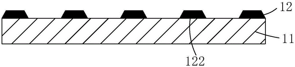
[0038] Step 1, such as figure 1 As shown, a substrate 11 is provided on which a black matrix 12 is formed.

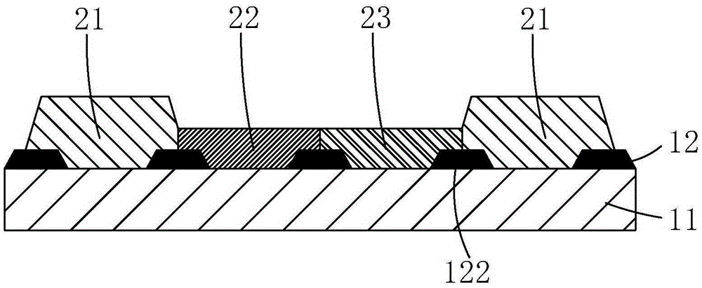
[0039] Step 2, such as figure 2As shown, several transparent color-resist blocks 21, several red color-resist blocks 22, and several green color-resist blocks 23 arranged in sequence are formed on the substrate 11 and the black matrix 12; wherein, every two adjacent A red color resistance block 22 and a green color resistance block 23 are arranged between the transparent color resistance blocks 21, and th...


PUM


Abstract

The invention provides a manufacturing method of a color filter substrate and the color filter substrate. The manufacturing method of the color filter substrate includes the steps that a red quantum dot and green quantum dot mixed layer is formed through a printing technology and overlaid with red color resistance blocks and green color resistance blocks, and transparent color resistance blocks are adopted to replace blue color resistance blocks and serve as a barrier wall of the red quantum dot and green quantum dot mixed layer, so that the three primary colors of red, green and blue are achieved under the blue backlight source, and accordingly color display is achieved. Compared with a traditional printing technology of the red quantum dot and green quantum dot mixed layer, a special barrier wall material is omitted, meanwhile a printable zone is relatively enlarged, and high-resolution printing manufacturing is facilitated. According to the color filter substrate, the red quantum dot and green quantum dot mixed layer overlaid with the red color resistance blocks and the green color resistance blocks is arranged, and the transparent color resistance blocks are adopted to replace the blue color resistance blocks and can serve as the barrier wall of the red quantum dot and green quantum dot mixed layer, so that the structure is simple and the production cost is low.

Description

technical field [0001] The invention relates to the field of display technology, in particular to a method for manufacturing a color filter substrate and the color filter substrate. Background technique [0002] The application of liquid crystal display (LCD, Liquid Crystal Display) has been popularized in people's daily life. With the continuous development and maturity of its technology, people have higher and higher requirements for its display performance and quality. A high-end product, high resolution, high penetration rate, wide color gamut, etc. At the same time, color filters (ColorFilter, CF) are very important components for LCDs, and the realization of these high-resolution, high-penetration, wide-color gamut products is mainly from the structure and materials of color filters. Let's get started. [0003] Due to its narrow half-wave width, high light efficiency, and wide color gamut, quantum dots (QuantumDot, QD) have been gradually developed and applied in the...

Claims


Application Information

Patent Timeline
Patent Type & Authority Applications(China)
IPC IPC(8): G02F1/1335
CPCG02F1/133514G02F1/133516
Inventor 刘虹唐敏
Owner TCL CHINA STAR OPTOELECTRONICS TECH CO LTD
Why Eureka
Try Eureka