Coal-sludge composite firing system based on dual-medium flue gas drying and circulating fluidized bed boiler

A circulating fluidized bed and dry sludge technology, applied in the direction of incinerator, combustion method, combustion type, etc., can solve the problems of complex system process, affecting the enthusiasm of power plant to incinerate sludge, and many equipments, and achieve the effect of simple system

Active Publication Date: 2016-01-20
UNIV OF SHANGHAI FOR SCI & TECH
View PDF5 Cites 9 Cited by
  • Summary
  • Abstract
  • Description
  • Claims
  • Application Information

AI Technical Summary

Benefits of technology

The technical effect of this new design for combustion systems that use both low or medium temperature exhaust gases from power plants combined with traditional methods like wet scrubbing processes are improved thermal efficacy while reducing emissions associated therewith. This results in more efficient energy utilization compared to current designs without these features.

Problems solved by technology

Technical Problem addressed in this patents relates to improving the efficient production and handling of waste materials containing various chemical elements like sulfur, nitrogen, metal oxides, ammonia, volatile compounds, cyanide, chromium, lead, zirconum dioxin, ceramics, iron pyrite, vanadium pentoxysulfonovanidazolithane(V) and tungsten trioxydisulfurine/dihydroxyferrumitronisodiumsolidified bacterial spargers called SNDGSDM, where each unit produces less than 1 ton of residual liquid per second compared to conventional techniques. Additionally, current sludges contain harmful gases including mercury, arsenious solvents, chlorocompound, formaldehydes, methylene diphenols, dimercaptans, trimmer oil components, and polytetrafluoroethanes (PTFE). These contaminant agents contribute to bad influences upon public health hazards caused by indoor sources. To address this problem, an improved method was proposed involving combination of multiple stages of sluccake decomposition and solid state ferric salt firing.

Method used


Image

  • Coal-sludge composite firing system based on dual-medium flue gas drying and circulating fluidized bed boiler

Examples


Embodiment Construction

[0020] The present invention will be further described below in conjunction with the accompanying drawings and embodiments.

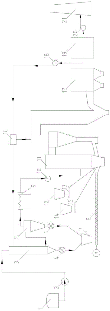
[0021] Such as figure 1 As shown, the coal-sludge co-combustion system based on two-medium flue gas drying and circulating fluidized bed boiler of the present invention includes sludge storage bin 1, screw pump 2, spray drying pipe 3, rotary feeder-4 , cyclone separator 5, rotary feeder 2 6, dry sludge bin 7, screw conveyor 8, cooling condenser 9, exhaust fan 10, circulating fluidized bed boiler 11, coal hopper 12, coal feeder 13 , limestone hopper 14, limestone feeder 15, mixing chamber 16, dust collector 17, cold smoke fan 18, desulfurization device 19, induced draft fan 20 and chimney 21.

[0022] The outlet of the coal feeder 12 is connected to the coal feeder 13, and the outlet of the coal feeder 13 is connected to the circulating fluidized bed boiler 11; the limestone hopper 14 is connected to the limestone feeder 15, and the outlet of the limest...


PUM


Abstract

The invention relates to a coal-sludge composite firing system based on a dual-medium flue gas drying and circulating fluidized bed boiler. A sludge storage bunker discharging outlet is connected with a feeding inlet of a spray drying pipe through a screw pump. A gas inlet of the spray drying pipe is connected with an outlet of a mixing chamber. An inlet of the mixing chamber is divided into two paths, wherein one path is connected with an outlet flue of a cyclone separator of the circulating fluidized bed boiler, and the other path is connected with an outlet of a dust remover through a cold smoke fan. A first outlet of the spray drying pipe is connected with a dry sludge bunker through a first rotary feeder. An outlet of the dry sludge bunker is connected with the circulating fluidized bed boiler through a spiral conveyor. A second outlet of the spray drying pipe is connected with the cyclone separator. A discharging outlet of the cyclone separator is connected with the dry sludge bunker through a second rotary feeder. An exhaust opening of the cyclone separator is connected with the circulating fluidized bed boiler through a cooling condenser and an exhaust gas fan in sequence. According to the coal-sludge composite firing system, sludge drying, dried tail gas waste heat utilization, sludge and coal composite firing, pollutant control and other functions can be achieved, odor and dust diffusion can be prevented, and the coal-sludge composite firing system has the beneficial effects of being simple, environment-friendly and efficient.

Description


Claims


Application Information

Patent Timeline
Owner UNIV OF SHANGHAI FOR SCI & TECH
Why Eureka
Try Eureka