
Metal rotor flowmeter with rectification function

A technology of metal rotor and flowmeter, which is applied in volume/mass flow generated by mechanical effects, volume measurement, liquid/fluid solid measurement, etc., and can solve the influence of measurement stability, impact bending of lower stop, length of rib force arm, etc. problems, to achieve the effect of improving measurement stability, reliability, and small rotation fluctuations

Inactive Publication Date: 2016-01-20
ZHEJIANG DIYUAN INSTR
View PDF7 Cites 4 Cited by
  • Summary
  • Abstract
  • Description
  • Claims
  • Application Information

AI Technical Summary

Problems solved by technology

[0007] (1) When the metal tube rotameter is installed downstream of the elbow or downstream of the valve, due to the influence of the elbow or valve, the flow field of the fluid varies greatly along the direction of the pipe diameter. This fluid impacts on the rotor (float) ), the rotor (float) receives unbalanced impact force in addition to the fluid impact force in the upper and lower directions, which causes the rotor (float) to fluctuate in the pipeline, and the measurement stability is affected
[0008] (2) The cavity of the lower stop of the conventional metal tube rotameter is composed of several pieces of reinforcing ribs divided into equal sectors. The large-diameter sector has a larger area. The default is straight through in mechanical manufacturing. When there are foreign objects in the fluid, foreign objects are easy to enter In the annular area, thus preventing the rotor from moving freely up and down
[0009] (3) In the large-diameter metal rotameter structure, the rotor (float) is large in size and very heavy in weight. During flow regulation, when the pipeline valve is suddenly closed or the pump is turned off, the metal rotor suddenly drops and directly impacts The bottom stop is on the top, and the large-diameter bottom stop has a long rib arm, so the moment is very large, and it is easy to bend the bottom stop, which directly leads to damage to the flowmeter

Method used


Image

  • Metal rotor flowmeter with rectification function
  • Metal rotor flowmeter with rectification function
  • Metal rotor flowmeter with rectification function

Examples


Embodiment 1

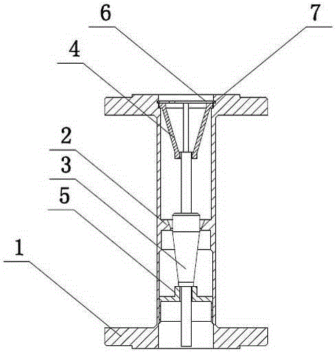
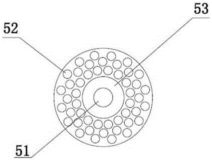
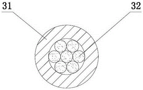
[0031] Embodiment 1: as figure 1 and figure 2 As shown, a metal rotameter with rectification function includes a pipe body 1, a rotor sleeve 2, a rotor 3, an upper stop 4 and a lower stop 5, wherein the rotor sleeve is an orifice. The rotor 3 is installed in the rotor sleeve 2, the rotor sleeve 2 is installed in the pipe body 1, the upper stop 4 and the lower stop 5 are respectively arranged at the upper port and the lower port of the pipe body, and the lower stop 5 is connected with the pipe body 1. Integral structure (it can be welded or integrally cast, inseparable), the upper stop 4 and the pipe body 1 are split structures (the two are independent parts, detachable), the upper stop 4 can be separated by a circlip 6 It is disassembled and installed in the tube body 1, and the inner edge of the tube body 1 is provided with a groove 7 that allows the snap spring 6 to snap in.

[0032] The center of the lower stopper 5 is provided with a guide hole 51 that allows the rotor ...

Embodiment 2

[0034] Embodiment 2: The rotor sleeve is a tapered tube. All the other are with embodiment 1.

[0035] Practical: When the fluid passes through the throttling parts in the pipeline (such as elbows, valves, and reducing pipes), the unstable flow field passes through the bottom stop from bottom to top, and the fluid passes through evenly distributed holes for rectification. Outflow, the larger foreign matter is blocked under the lower stop, and the rectified fluid impacts the metal rotor again, and generates a force on the metal rotor (the magnitude of this force varies with the flow rate); when the flow rate is large enough, The resulting force lifts the rotor up and raises it. When the rotor is in a balanced state, it stays at a certain height.


PUM


Abstract

The invention discloses a metal rotor flowmeter with a rectification function. The metal rotor flowmeter comprises a pipe body, a rotor sleeve, a rotor, an upper stop and a lower stop. A guiding hole allowing the rotor to extend therein is arranged at the center of the lower stop, the periphery of the guiding hole is provided with at least one ring of a plurality of sieving apertures enclosing a circumference, and a heightening boss is additionally arranged between the guiding hole and somewhere nearby the ring of the sieving apertures. According to the invention, a dense grid plate structure with multiple small circular holes in uniform circumferential distribution is employed, under the condition that the accumulated flow passage area of all the small holes is not decreased, current stabilization effect is applied on a fluid, when the fluid passes through such throttling members as a bend, a valve, a reducing pipe and the like, instability is caused to the flow field of the fluid due to the effect of the throttling members, and after passing through a porous current-limiting orifice plate, the fluid is rectified again, such that the requirement of the metal rotor flowmeter for a straight pipe segment is lowered, and the working condition adaptation scope of the metal rotor flowmeter is enlarged under the condition that the measurement stability is enhanced.

Description

technical field [0001] The invention relates to the technical field of metal rotameters, in particular to a metal rotameter with rectification function. Background technique [0002] Metal rotameters are divided into orifice type and cone type structure: [0003] (1) Orifice plate metal rotameter, such as the patent CN201420551905.3, is mainly composed of two parts, one is the orifice throttling part embedded in the flow tube, and the other is the The conical rotor (float) that moves freely up and down. When the rotameter measures the flow of the fluid, the measured fluid flows in from the lower end of the orifice plate. The flow of the fluid impacts the rotor and generates a force on it (the magnitude of this force varies with The size of the flow varies); when the flow is large enough, the generated force will lift the rotor and make it rise. At the same time, the measured fluid flows through the annular section between the rotor and the inner hole of the orifice plate, ...

Claims


Application Information

Patent Timeline
Patent Type & Authority Applications(China)
IPC IPC(8): G01F15/12G01F1/52
Inventor 孙向东聂志刚
Owner ZHEJIANG DIYUAN INSTR
Learn More