
Pre-distortion method and device for power amplifier and radio frequency system

A technology of power amplifier and power amplification, which is applied in the direction of power amplifier and improved amplifier to reduce nonlinear distortion, etc. It can solve the problems of difficult realization of system feedback synchronization control, distortion of radio frequency signal, and small application range.

Inactive Publication Date: 2016-01-20
NO 30 INST OF CHINA ELECTRONIC TECH GRP CORP
View PDF4 Cites 8 Cited by
  • Summary
  • Abstract
  • Description
  • Claims
  • Application Information

AI Technical Summary

Problems solved by technology

However, power amplifiers usually exhibit nonlinearity, so how to eliminate the distortion of radio frequency signals caused by the nonlinearity of power amplifiers is very important
[0003] In the prior art, for a power amplifier whose input signal is a variable envelope signal, its linearization techniques usually include feedback method and feedforward method, but the feedback method is only applicable when the input signal is a low-frequency signal, because the input signal When it is a high-frequency signal, it is difficult to realize the synchronous control of the system feedback, and the scope of application is small
However, the correction loop of the feedforward system using the feedforward method needs to add an auxiliary error amplifier, which greatly increases the cost of the system and reduces the efficiency of radio frequency transmission.

Method used


Image

  • Pre-distortion method and device for power amplifier and radio frequency system
  • Pre-distortion method and device for power amplifier and radio frequency system
  • Pre-distortion method and device for power amplifier and radio frequency system

Examples


Embodiment Construction

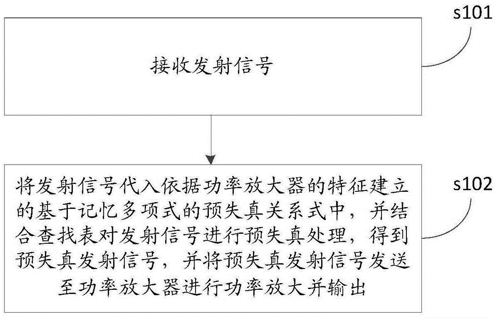
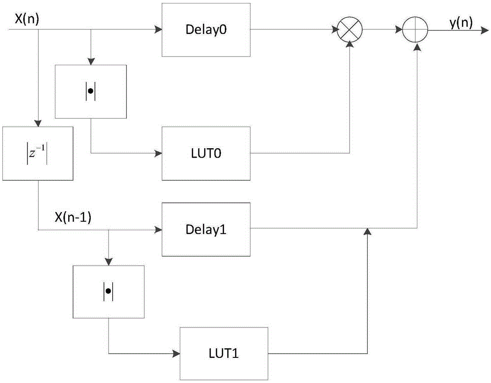
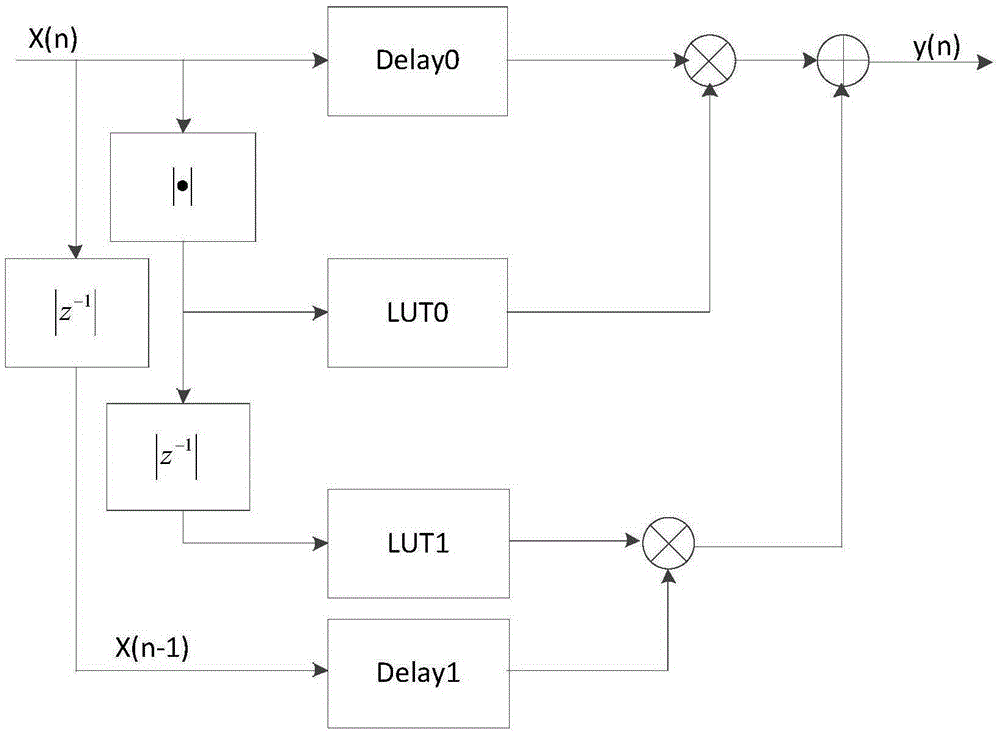
[0045] The core of the present invention is to provide a pre-distortion method for a power amplifier. Before sending the transmission signal x(k) to the power amplifier, the transmission signal x( k) performing pre-distortion processing, offsetting the distortion caused by the nonlinearity of the power amplifier when the pre-distorted transmission signal y(k) passes through the power amplifier, ensuring the optimal performance of the transmission signal x(k) transmission, improving the radio frequency transmission efficiency and The scope of application is wide; another core of the present invention is to provide a predistortion device and a radio frequency system of a power amplifier.

[0046] In order to make the purpose, technical solutions and advantages of the embodiments of the present invention clearer, the technical solutions in the embodiments of the present invention will be clearly and completely described below in conjunction with the drawings in the embodiments of ...


PUM


Abstract

The invention discloses a pre-distortion method for a power amplifier. The pre-distortion method includes the steps that transmitting signals x(k) are received; the transmitting signals x(k) are substituted into a pre-distortion relational expression which is established according to the characteristics of the power amplifier and is based on a memory polynomial, the transmitting signals x(k) are subjected to pre-distortion in combination with a lookup table, pre-distorted transmitting signals y(k) are obtained, and the pre-distorted transmitting signals y(k) are sent to the power amplifier for power amplification and output. It is thus clear that before the transmitting signals x(k) are sent to the power amplifier, the transmitting signals x(k) are subjected to pre-distortion through the pre-distortion relational expression which is established according to the characteristics of the power amplifier and is based on the memory polynomial, distortion caused by non-linearity of the power amplifier and generated when the pre-distorted transmitting signals y(k) pass through the power amplifier is offset, optimal performance transmission of the transmitting signals x(k) is guaranteed, radio frequency transmitting efficiency is improved, and the application range is wide. The invention further discloses a pre-distortion device for the power amplifier and a radio frequency system.

Description

technical field [0001] The invention relates to the technical field of signal predistortion, in particular to a predistortion method, device and radio frequency system of a power amplifier. Background technique [0002] With the development of communication technology, the requirements for RF power amplifiers are getting higher and higher. In order to avoid the out-of-band radiation interference caused by the nonlinearity of the RF system circuit, the RF system is required to be in a linear working state. From the perspective of complexity and cost, the linearization of the power amplifier plays a decisive role in the linearization of the radio frequency system. However, the power amplifier usually exhibits nonlinearity, so how to eliminate the distortion of the radio frequency signal caused by the nonlinearity of the power amplifier is very important. [0003] In the prior art, for a power amplifier whose input signal is a variable envelope signal, its linearization techni...

Claims


Application Information

Patent Timeline
IPC IPC(8): H03F1/32H03F3/20
Inventor 任小军袁凤国李路谈江海
Owner NO 30 INST OF CHINA ELECTRONIC TECH GRP CORP
Learn More