Electrically actuated rotary drive device

A rotary drive device, electrical manipulation technology, applied in the direction of transmission, electromechanical device, gear transmission, etc., can solve the problems affecting the compactness of the rotary drive device.

Active Publication Date: 2016-01-20
FESTO AG & CO KG
View PDF5 Cites 4 Cited by
  • Summary
  • Abstract
  • Description
  • Claims
  • Application Information

AI Technical Summary

Problems solved by technology

However, this is problematic if the rotary drive is to be operated only purely electrically, since the required drive motor is then of greater size due to the increased power requirement, which affects the compactness of the rotary drive

Method used


Image

  • Electrically actuated rotary drive device
  • Electrically actuated rotary drive device
  • Electrically actuated rotary drive device

Examples


Embodiment Construction

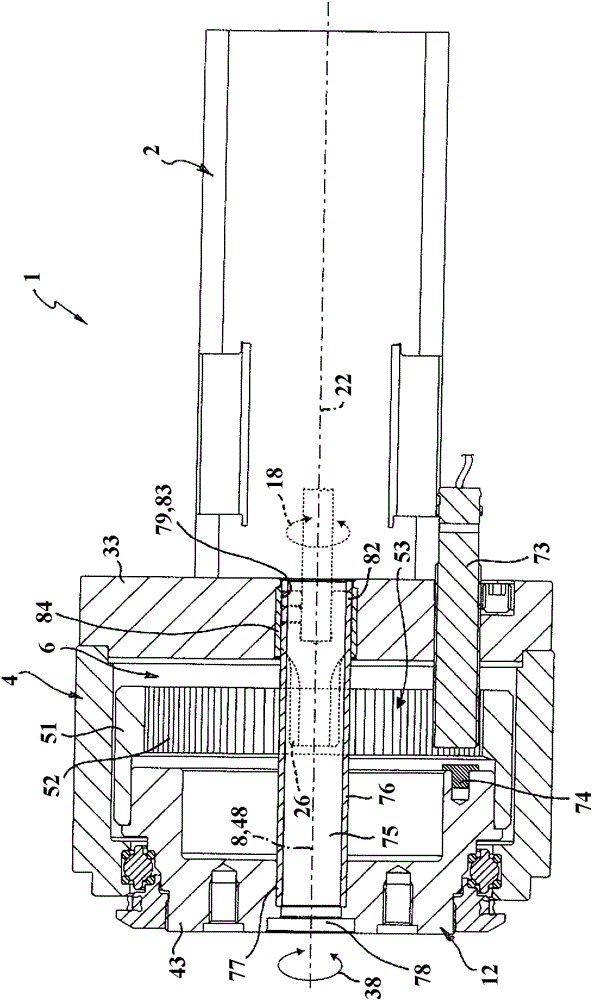
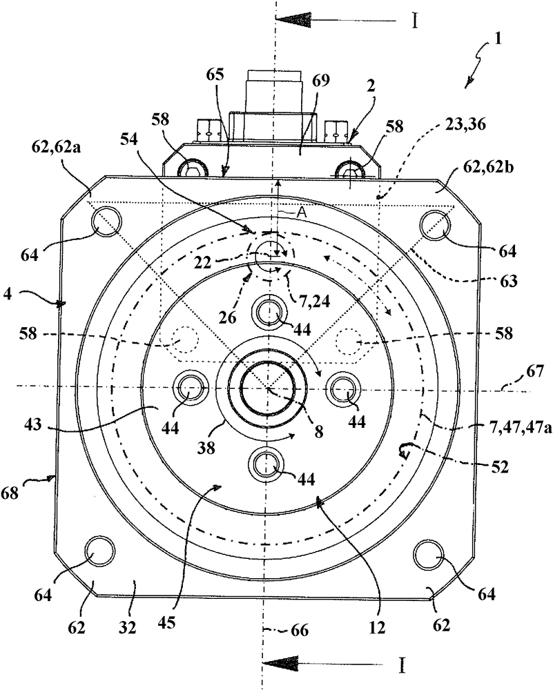
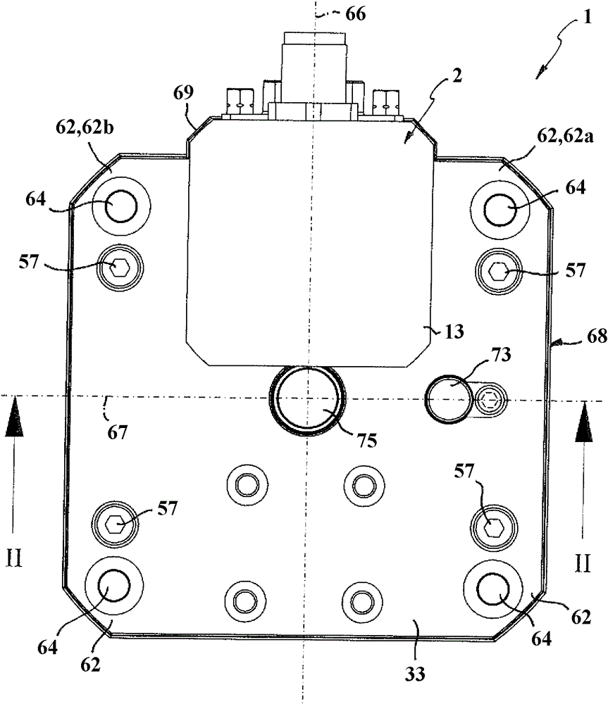
[0032] The electrically actuable rotary drive, which is designated in its entirety by the reference numeral 1 , has an electric drive motor 2 as a drive source, which is mounted on the rear side 3 b of the gear housing 4 of the rotary drive 1 . The gear housing 4 has an imaginary main axis 5 and a front side 3 a oriented opposite to the rear side 3 b , wherein both the front side 3 a and the rear side 3 b are oriented in the axial direction of the main axis 5 .

[0033]The gear housing 4 encloses an inner space which is referred to below as the gear chamber 6 . In this transmission chamber 6 there is a transmission part 7 of a gear transmission, which establishes a drive connection between the drive motor 2 and an output part 12 mounted rotatably about an axis of rotation 8 on the transmission housing 4 .

[0034] The axis of rotation 8 of the driven element 12 has the same orientation as the main axis 5 .

[0035] The electric drive motor 2 has a motor housing 13 which prefe...


PUM


Abstract

The invention relates to an electrically actuated rotary drive device (1), which has a gearing housing (4), to a rear side of which an electric drive motor (2) is fastened and on which an output part (12) having a drive connection to the drive motor (2) is rotatably supported. The drive connection is realised by gearing means (7) arranged in the gearing housing (4), which gearing means comprise an output gear (47), which is arranged on the output part (12) and is designed as a ring gear (47a) having internal teeth (52), and a drive pinion (24), which is provided with external teeth (26) and belongs to the drive motor (2). The drive pinion (24) protrudes into the ring gear (47a) inside the gearing housing (4).

Description

technical field [0001] The invention relates to an electrically actuated rotary drive with a gear housing having a front side and a rear side opposite to this, on which is rotatably mounted a front side of the gear housing. A follower on the side, which is in driving connection with a driven gear rotatably arranged in the transmission housing, a drive pinion of an electric drive motor arranged externally on the rear side of the transmission housing Meshing with the driven gear. Background technique [0002] Rotary drives of this type are known from DE 10 2011 107 012 A1 and are equipped with hybrid drive technology and include, in addition to electric drive motors, also hydrodynamically actuable drives, wherein both the drive motor and the fluidly actuable drive act on the to the follower accessible at the front side of the gear housing to put it into rotational movement. The force flow between the drive motor mounted on the rear side on the gear housing and the driven par...

Claims


Application Information

Patent Timeline
Patent Type & Authority Applications(China)
IPC IPC(8): F16H1/10F15B15/12
CPCF16H1/10H02K7/1163H02K7/116
Inventor G.托瓦尔特
Owner FESTO AG & CO KG
Why Eureka
Try Eureka