
Continuous flow photochemical reactor device

A chemical reactor and reactor technology, applied in chemical/physical/physical-chemical reactors, chemical instruments and methods, chemical/physical processes, etc., can solve problems such as affecting reaction temperature, limiting application scope, and complex switching power supply connections

Active Publication Date: 2021-07-06
DALIAN UNIV OF TECH
View PDF9 Cites 2 Cited by
  • Summary
  • Abstract
  • Description
  • Claims
  • Application Information

AI Technical Summary

Problems solved by technology

[0004] Many new photochemical synthesis reactions require precise control of reaction conditions, such as the wavelength of light, the size of the optical power density, and temperature, etc., while ordinary photochemical reaction equipment uses reactors and water cooling, complex devices, and continuous flow reactions cannot be achieved. The reaction conditions such as reaction temperature, wavelength, and optical power density cannot be finely controlled
[0005] Patent 202010171581.0 discloses a multifunctional continuous flow synthesis device. Although it can perform photochemical reactions, since the light source is not equipped with a heat sink in this device, the heat emitted by the lamp beads will affect the reaction temperature and affect the experimental data. Accuracy, the light source adopts DC power supply, the connection with switching power supply is more complicated, and the voltage provided is low, the optical power of the lamp bead is not high, which leads to low optical power density value, which limits the application range, and the optical power density The value is fixed, and it is impossible to explore the influence of different optical power density values ​​on the photochemical reaction catalytic effect. The wavelength of the light source is fixed, and only the photochemical reaction excited by a specific wavelength can be explored, and it is impossible to realize the unknown photochemical reaction. optimal wavelength

Method used


Image

  • Continuous flow photochemical reactor device
  • Continuous flow photochemical reactor device
  • Continuous flow photochemical reactor device

Examples


Embodiment 1

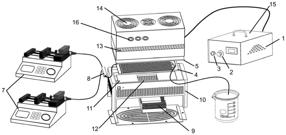
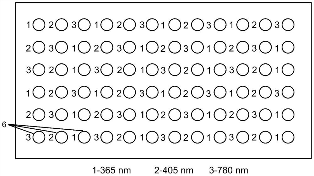
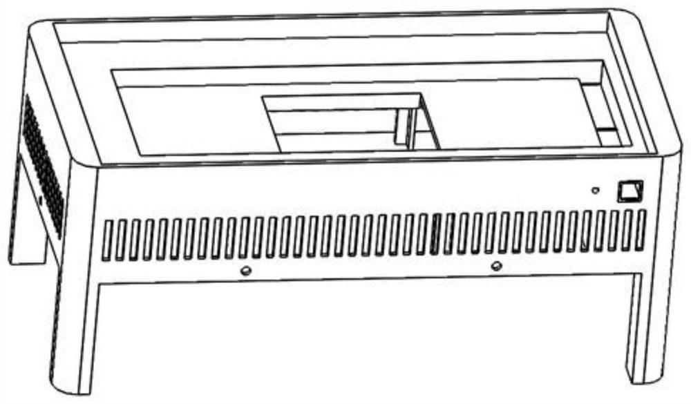
[0029] A continuous flow photochemical reactor device, including a light control unit, a reaction unit, and a temperature control unit; the light control unit includes an optical power regulator 1; the optical power regulator includes a sliding resistor, an adjustment knob 2, a control switch 3, and an AC power supply The AC input range of the AC power supply is 110-270V; the sliding resistor and the AC power supply are placed in the housing 15 of the optical power regulator, the adjustment knob and the control switch are arranged outside the housing of the optical power regulator, and the sliding resistor, The adjustment knob, the control switch, and the AC power supply are all electrically connected; the reaction unit includes a microreactor 4 and an LED lamp board 5; the LED lamp board is placed above the microreactor and connected in series with the sliding resistor and the AC power supply; The light board of the LED is composed of a plurality of LED lamp beads 6 arranged (...

Embodiment 3

[0039] Select the reaction of Example 2, keep the other conditions of the reactor, micro-mixer and micro-flow tube unchanged, adopt a three-wave mixed light source of 365nm, 405nm, and 780nm, press the control switch in the light control unit, and control the wavelength switch. The wavelength of the LED light board is required; the optical power density value is adjusted to 70mW / cm through the dimmer knob 2 ;Wavelength switch to change the wavelength, at a flow rate of 1000μL / min, the three wavelengths, when the retention time is 180s, the yields are 67%, 96%, 33%, respectively, indicating that the wavelength of the light source affects the catalytic effect of the photochemical reaction, 405nm is the optimum wavelength for this reaction.

Embodiment 4

[0041] Select the reaction of Example 2, keep other conditions such as the micro-mixer and the micro-flow tube unchanged, the fixed wavelength is 405nm, adjust the sliding resistor by adjusting the knob, and adjust to the optical power density value of 20mW / cm respectively 2 , 40mW / cm 2 , 70mW / cm 2 , 100mW / cm 2 , under the reaction condition of 1000μL / min flow rate, when the retention time is 180s, the reaction yields are 33%, 56%, 96%, 98%, respectively, indicating that the photochemical reaction yield increases rapidly with the increase of optical power density, Then it increases slowly with the increase of optical power density.


PUM

PropertyMeasurementUnit
Wavelengthaaaaaaaaaa
Optical power densityaaaaaaaaaa
Inner diameter sizeaaaaaaaaaa

Abstract

The invention relates to the technical field of photochemical reaction equipment, in particular to a continuous flow photochemical reactor device. The device comprises a light control unit, a reaction unit and a temperature control unit, wherein the light control unit comprises a light power regulator; the light power regulator comprises a sliding resistor, a regulating knob, a control switch and an alternating current power supply; the reaction unit comprises a microreactor and a lamp panel; the lamp panel is arranged above the microreactor and is connected in series with the sliding resistor and the alternating current power supply; the lamp panel is composed of a plurality of lamp beads, the lamp beads comprise lamp beads with single wavelength arranged or lamp beads with different wavelengths alternately arranged, the wavelength of the lamp beads is 365-780 nm, and the optical power density of the lamp panel is 0-500 mW / cm < 2 >; when the wavelengths of the lamp beads are different, wavelength switches for correspondingly controlling the lamp beads are arranged; the temperature control unit comprises a refrigeration module and a heating module and is used for controlling the reaction temperature of the microreactor. According to the device, the wavelength of the light source can be adjusted, the optical power density value can be adjusted, and research on photochemical reactions is facilitated.

Description

technical field [0001] The invention relates to the technical field of photochemical reaction equipment, in particular to a detachable, temperature-controllable, adjustable light wavelength and light power density, and modular light continuous flow photochemical reactor device. Background technique [0002] Photochemical reactions not only have great potential value in the environmental field of catalytic degradation of pollutants, but also are an important technical means for the synthesis of high-value pharmaceutical intermediates. [0003] Continuous flow chemistry can realize precise control of reaction conditions, such as reaction time, retention time, reaction temperature, amount of reactants, material mixing and other conditions, which realizes the combination of independent and separate synthetic reaction operations in traditional chemical engineering, Furthermore, the speed of reaction synthesis is accelerated, especially for highly dangerous and difficult-to-synthe...

Claims


Application Information

Patent Timeline
IPC IPC(8): B01J19/12B01J19/00
CPCB01J19/127B01J19/0093B01J19/0013Y02W10/37
Inventor 张利静陶胜洋郑晓龙张秋楠
Owner DALIAN UNIV OF TECH
Learn More