Gas and steam turbine installation and method for operating the same

A technology of steam turbines and gas turbines, which is applied in the direction of gas turbine devices, steam engine devices, jet propulsion devices, etc., and can solve problems such as large space locations

Active Publication Date: 2008-07-09
SIEMENS ENERGY GLOBAL GMBH CO & KG
View PDF0 Cites 3 Cited by
  • Summary
  • Abstract
  • Description
  • Claims
  • Application Information

AI Technical Summary

Problems solved by technology

Finally, gas and steam turbine installations in a multi-sha

Method used


Image

  • Gas and steam turbine installation and method for operating the same
  • Gas and steam turbine installation and method for operating the same

Examples


Embodiment Construction

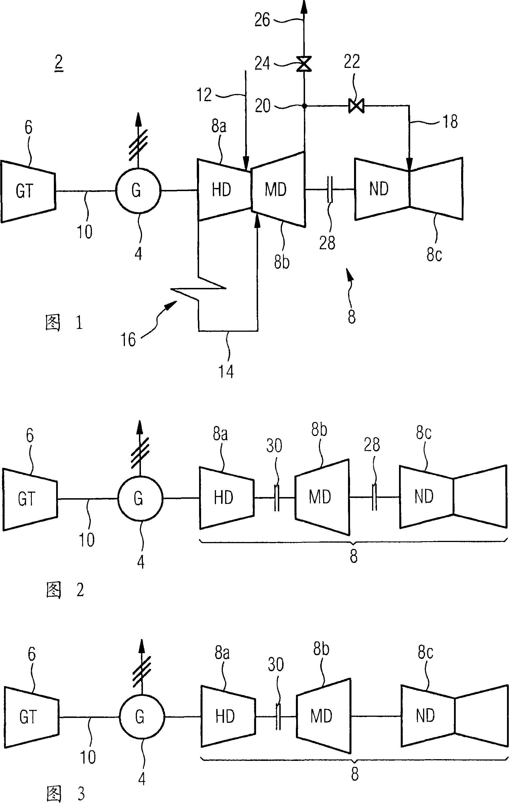
[0023] The gas and steam turbine plant 2 shown in Figure 1 is an integral part of the GuD power plant. In order to effectively utilize the primary energy of minerals, a thermally coupled GuD device is used. The gas and steam turbine plant 2 for this purpose has a generator 4, a gas turbine 6 and a steam turbine 8. The steam turbine 8 here includes a high-pressure stage 8a, an intermediate-pressure stage 8b, and a low-pressure stage 8c. Their respective pressure states during operation are also marked with the letters HD, MD or ND in Figure 1. The hot exhaust gas formed when a fossil fuel is burned in the gas turbine 6 is used to heat a waste steam boiler not shown in the figure, and steam for operating the steam turbine 8 is generated in the waste steam boiler through the vaporization of water. The gas turbine 6, the steam turbine 8, and the generator 4 are connected one after another on a shaft 10 oriented along a common axis in a so-called single-shaft arrangement structure. In ...


PUM


Abstract

Gas and steam turbine installation has generator (4), gas turbine (6) and steam turbine (8), which are arranged on a shaft (10) having plurality of shaft sections. The steam turbine comprises high-pressure stage (8a) and a low-pressure stage (8c), associated with respective shaft sections. The shaft section associated with the low-pressure stage is disposed at the end of the shaft. One coupling (28) is provided between the shaft section of the high-pressure stage and the shaft section of the low-pressure stage. An independent claim is also included for the method for operating gas and steam turbine installation.

Description

Technical field [0001] The invention relates to a gas and steam turbine device including a generator, a gas turbine and a steam turbine. In addition, the invention also relates to a method of operating such a device. Background technique [0002] In gas and steam turbine installations, the high-temperature exhaust gas from the gas turbine is used to heat a so-called exhaust gas boiler, which vaporizes liquid water to produce the steam needed to run the steam turbine. Gas turbines and steam turbines are usually used in this case to drive one or more electric generators. By making full use of the waste heat contained in the gas turbine exhaust gas, it is possible to achieve a particularly high overall efficiency in this combined gas and steam turbine plant and thus save fuel. This is not only from a purely economic point of view, but also in environmental protection and environmental protection. It also plays an increasingly important role in the sense of caring for natural resourc...

Claims


Application Information

Patent Timeline
IPC IPC(8): F02C6/18F02C7/36F01K23/16
CPCF02C6/18F02C7/36F05D2220/72F05D2220/76Y02E20/14Y02E20/16
Inventor 赫伯特·舒茨霍尔格-马克斯·恩伯格马丁·温伯格
Owner SIEMENS ENERGY GLOBAL GMBH CO & KG
Why Eureka
Try Eureka