Gas and steam turbine installation and method for operating the same

A technology for steam turbines and gas turbines, which is applied in gas turbine installations, steam engine installations, jet propulsion installations, etc., and can solve problems such as large space locations

Active Publication Date: 2009-12-02
SIEMENS ENERGY GLOBAL GMBH CO & KG
View PDF3 Cites 0 Cited by
  • Summary
  • Abstract
  • Description
  • Claims
  • Application Information

AI Technical Summary

Problems solved by technology

Finally, gas and steam turbine installations in a multi-shaft configuration require relatively large spatial locations

Method used


Image

  • Gas and steam turbine installation and method for operating the same
  • Gas and steam turbine installation and method for operating the same
  • Gas and steam turbine installation and method for operating the same

Examples


Embodiment Construction

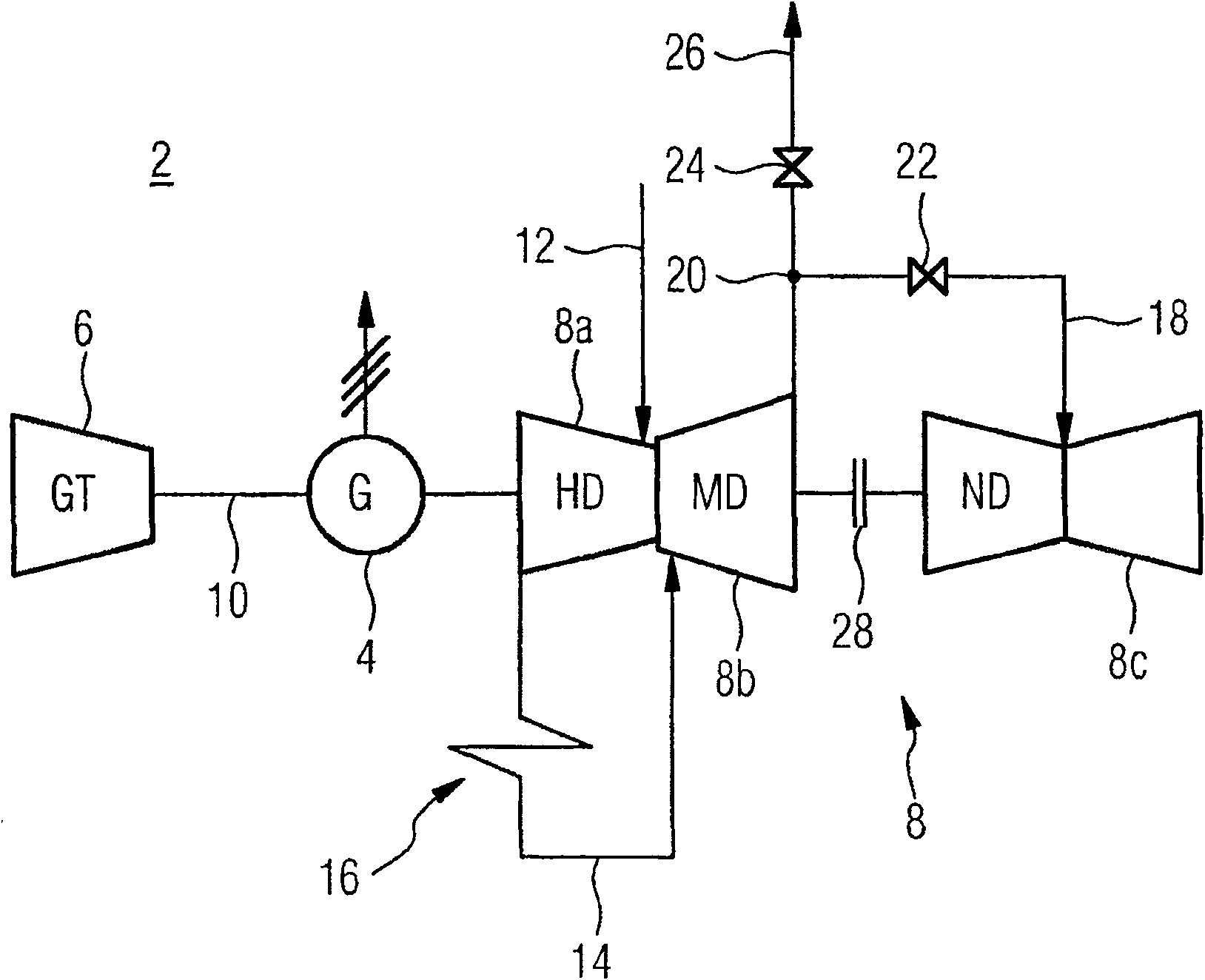
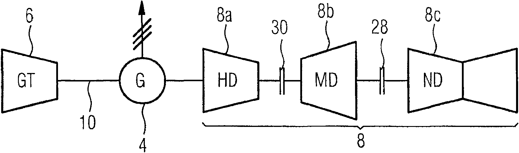
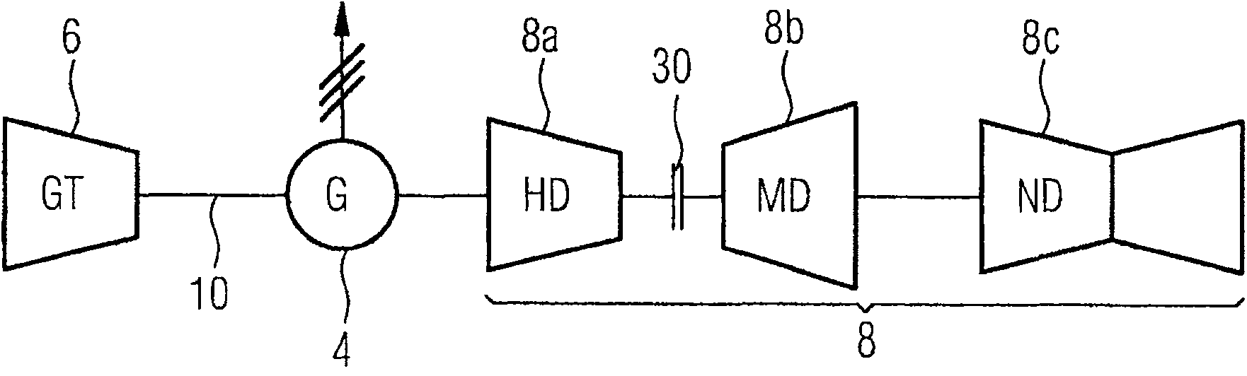
[0023] figure 1 The gas and steam turbine plant 2 shown is an integral part of the GuD power plant. In order to utilize the primary energy of the minerals particularly efficiently, a GuD unit is used which is coupled thermodynamically. For this purpose the gas and steam turbine plant 2 has a generator 4 , a gas turbine 6 and a steam turbine 8 . The steam turbine 8 here comprises a high-pressure stage 8a, a medium-pressure stage 8b and a low-pressure stage 8c. Their respective pressure states that exist during operation are in the figure 1 Also marked with the letters HD, MD or ND. The hot exhaust gas formed during the combustion of a fossil fuel in the gas turbine 6 is used to heat an exhaust steam boiler (not shown in the figure), in which steam is generated for operating the steam turbine 8 by evaporating water. The gas turbine 6, the steam turbine 8 and the generator 4 are successively connected on a shaft 10 oriented along a common axis according to a so-called singl...


PUM


Abstract

Gas and steam turbine installation has generator (4), gas turbine (6) and steam turbine (8), which are arranged on a shaft (10) having plurality of shaft sections. The steam turbine comprises high-pressure stage (8a) and a low-pressure stage (8c), associated with respective shaft sections. The shaft section associated with the low-pressure stage is disposed at the end of the shaft. One coupling (28) is provided between the shaft section of the high-pressure stage and the shaft section of the low-pressure stage. An independent claim is also included for the method for operating gas and steam turbine installation.

Description

technical field [0001] The invention relates to a gas and steam turbine installation comprising an electric generator, a gas turbine and a steam turbine. Furthermore, the invention relates to a method for operating such a device. Background technique [0002] In gas and steam turbine installations, the high-temperature exhaust gas from the gas turbine is used to heat a so-called exhaust gas boiler, which generates the steam required to operate the steam turbine by vaporizing liquid water. Gas and steam turbines are typically used in this case to drive one or more generators that generate electrical energy. By making full use of the waste heat contained in the exhaust gas of the gas turbine, a particularly high overall efficiency and thus fuel savings can be achieved in such combined gas and steam turbine installations, not only from a purely economic point of view, but also in terms of environmental protection and The sense of caring for natural resources is also playing a...

Claims


Application Information

Patent Timeline
Patent Type & Authority Patents(China)
IPC IPC(8): F02C6/18F02C7/36F01K23/16
CPCF05D2220/76Y02E20/16F02C6/18Y02E20/18F02C7/36F05D2220/72Y02E20/14
Inventor 赫伯特·舒茨霍尔格-马克斯·恩伯格马丁·温伯格
Owner SIEMENS ENERGY GLOBAL GMBH CO & KG
Why Eureka
Try Eureka